Wednesday, November 12, 2014
12V Speed Dimmer Controller Diagram Circuit
SILICON CHIP has produced a number of DC speed controllers over the years, the most recent being our high-power 24V 40A design featured in the March & April 2008 issues. Another very popular design is our 12V/24V 20A design featured in the June 1997 issue and we have also featured a number of reversible 12V designs.Circuit looks like:
For many applications though, most of these designs are over-kill and a much simpler circuit will suffice. Which is why we are presenting this basic design which uses a 7555 timer IC, a Mosfet and not much else. Being a simple design, it does not monitor motor back-EMF to provide improved speed regulation and nor does it have any fancy overload protection apart from a fuse. However, it is a very efficient circuit and the kit cost is quite low.Parts layout:
There are many applications for this circuit which will all be based on 12V motors, fans or lamps. You can use it in cars, boats, and recreational vehicles, in model boats and model railways and so on. Want to control a 12V fan in a car, caravan or computer? This circuit will do it for you.Circuit diagram:
The circuit uses a 7555 timer (IC1) to generate variable width pulses at about 210Hz. This drives Mosfet Q3 (via transistors Q1 & Q2) to control the speed of a motor or to dim an incandescent lamp.Halogen lamps:While the circuit can dim 12V halogen lamps, we should point out that dimming halogen lamps is very wasteful. In situations where you need dimmable 12V lamps, you will be much better off substituting 12V LED lamps which are now readily available in standard bayonet, miniature Edison screw (MES) and MR16 halogen bases. Not only are these LED replacement lamps much more efficient than halogen lamps, they do not get anywhere near as hot and will also last a great deal longer.
Source: Silicon Chip 15 November 2008
Mini Subwoofer 5″ – 6″ BandPass 4th Order Isobaric
The order of 4 or sealed rear chamber bandpass system is essentially a system of watertight enclosures with the addition of an acoustic filter for the driver. The resulting system usually provides a lower cut-off frequency, the compromise that a larger case. The space can be reduced by two drivers in isobaric configuration.
4th-order bandpass systems generally show better able to handle the functions that the other major systems are considered. The transient response and is second only to the sealed enclosure systems, making it a good choice for subwoofer applications.
Since all output 4th order bandpass system is via the port, the largest diameter possible for the port area should be used to minimize noise from the port. The ports must be incinerated where possible, for the same reasons.

The 4th order bandpass system rarely allows a perfect bandpass response - there is usually an out-of-band noise present in the production. A notch filter can be used simply to reduce the noise as audible. Otherwise, a lowpass filter used in series with the driver, but the in-band response system may be affected if this approach is taken.
As the speaker sound 4th order band pass issued by the openings or ports on the port side of the box, the port noise inevitable.
This unwanted noise can be minimized by a notch filter and the largest diameter possible for the port of the area should definitely be used. Another option is to burn the ports of the 4th order bandpass room as this will certainly help to reduce unwanted extra from the subwoofer.
Mini SubWoofer Power Amplifier clik for detail
WOOFER / MID MODEL - 5MP60 / N
Specifications
Nominal Basket Diameter 5 "/ 125mm
Impedance 8 ohm
RMS Power 50 Watts
Program Power 100 Watts
Frequency response 50Hz - 12.0kHz
Sensitivity (1W/1m) 91dB
Voice Coil Diameter 1 "/ 25.8mm
BL Factor 6.4 N / A
Voice Coil Length 14 mm
Air Gap Height 6mm
X Damage (peak to peak) 20 mm
Magnetic Assembly Weight 2.2 lbs / 1.0 kg.
Edit Information
Diameter 5.28 "/ 134mm x 5.28" / 134mm
Bolt Circle Diameter 5.4 "/ 137mm
Baffle Cutout Diameter --
- Front Mount 4.72 "/ 120mm
Many of the 4 mounting holes
Volume displaced by driver, 019 m 3 / .5 liter
Total Depth 2.68 "/ 68mm
Net weight 2.64 lbs / 1.2 kg.
Weight 2.8 lbs / 1.27 kg.
Materials
Basketball aluminum diecast
Polypropylene cone
Rubber Surround
Voice Coil Wire Copper
Ferrite
Thiele-Small Parameters
Resonance Frequency (FS) 60 Hz
Impedance (Re) 5.33 ohms
Coil Inductance (Le) 0.4 mH
Mechanical Q (Qms) 1.604
Electrical Factor (Qes) .35
Total Q (Qts) .29
Comp. Equivalent Vol. (Vas) 35 FT3 / 9.8 Liter
Voice Coil Overhang (Xmax) 4.0mm
Reference yield 5%
Volume Displacement 34 cm3
Rc servo controller circuit using PIC18F252
Rc servo controller circuit using PIC18F252
rc servo controller circuit
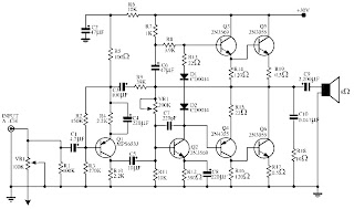
25 Watt Audio Amplifier Circuit
Circuit diagram:
Parts:R1 = 47K
R2 = 4K7
R3 = 1K5
R4 = 47K
R5 = 390R
R6 = 470R
R7 = 33K
R8 = 150K
R9 = 15K
R10 = 27R
R11 = 500R-1/2W
R12 = 10R
R13 = 10R
R14 = 220R
R15 = 220R
R16 = 10R
R17 = 8.2R-2W
R18 = 22R-4W(wirewound)
C1 = 470nF-63V
C2 = 330pF-63V
C3 = 470µF-63V
C4 = 100nF-63V
C5 = 470µF-63V
C6 = 100nF-63V
C7 = 100µF-25V
C8 = 100nF-63V
C9 = 10pF-63V
C10 = 1µF-63V
C11 = 100nF-63V
Q1 = BC560C
Q2 = BC560C
Q3 = BC560C
Q4 = BC560C
Q5 = BC560C
Q6 = BD140
Q7 = BD139
Q8 = IRF530
Q9 = IRF9530
Power supply section:

Power supply circuit diagram:
Parts:R1 = 3K3-1/2W
C1 = 10nF-1000V
C2 = 4700µF-50V
C3 = 4700µF-50V
C4 = 100nF-63V
C5 = 100nF-63V
D1 = 200V 8A Diode bridge
D2 = 5mm. Red LED
F2 = 3.15A Fuses with sockets
F2 = 3.15A Fuses with sockets
T1 = 220V Primary, 25 + 25V Secondary 120VA Mains transformer
PL1 = Male Mains plug
SW1 = SPST Mains switch
Notes:
- Can be directly connected to CD players, tuners and tape recorders. Simply add a 10K Log potentiometer (dual gang for stereo) and a switch to cope with the various sources you need.
- Q6 & Q7 must have a small U-shaped heatsink.
- Q8 & Q9 must be mounted on heatsink.
- Adjust R11 to set quiescent current at 100mA (best measured with an Avo-meter connected in series to Q8 Drain) with no input signal.
- A correct grounding is very important to eliminate hum and ground loops. Connect to the same point the ground sides of R1, R4, R9, C3 to C8. Connect C11 to output ground. Then connect separately the input and output grounds to power supply ground.
- An earlier prototype of this amplifier was recently inspected and tested again after 15 years of use. Results, comments and pictures are shown here.
Tuesday, November 11, 2014
Simple Solar Tracking System
Fig. 1: Circuit of solar tracking system |
Fig. 1 shows the circuit of the solar tracking system. The solar tracker comprises comparator IC LM339, H-bridge motor driver IC L293D (IC2) and a few discrete components. Light-dependent resistors LDR1 through LDR4 are used as sensors to detect the panel’s position relative to the sun. These provide the signal to motor driver IC2 to move the solar panel in the sun’s direction. LDR1 and LDR2 are fixed at the edges of the solar panel along the X axis, and connected to comparators A1 and A2, respectively. Presets VR1 and VR2 are set to get low comparator output at pins 2 and 1 of comparators A1 and A2, respectively, so as to stop motor M1 when the sun’s rays are perpendicular to the solar panel.
When LDR2 receives more light than LDR1, it offers lower resistance than LDR1, providing a high input to comparators A1 and A2 at pins 4 and 7, respectively. As a result, output pin 1 of comparator A2 goes high to rotate motor M1 in one direction (say, anti-clockwise) and turn the solar panel.
When LDR1 receives more light than LDR2, it offers lower resistance than LDR2, giving a low input to comparators A1 and A2 at pins 4 and 7, respectively. As the voltage at pin 5 of comparator A1 is now higher than the voltage at its pin 4, its output pin 2 goes high. As a result, motor M1 rotates in the opposite direction (say, clock-wise) and the solar panel turns.
Fig. 2 Proposed assembly for the solar tracking system |


 As the amplifier circuit also uses a number of frequencies to drive the loudspeaker, the bass frequencies will be reduced. Therefore need to be plugged the bass-boost control at fedback loop amplifier, this is done to overcome the decline in quality.


