Showing posts with label audio. Show all posts

Friday, December 12, 2014

Stereo Audio Power Amplifier 20 Watt

20watt-power-amplifier

Here is a reliably high sound quality audio power amplifier project based on the National Semiconductor’s LM1875 IC.The circuit that we give is a similar form of the application circuit in the datasheet that NS provides. It is really easy to build and low cost.    
Read More..

Audio power amplifier circuit 140 W

schematic-diagram-power-amplifier


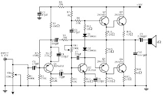
This simple schematic shows a 140W Audio power amplifier circuit by using 2N3569, 2N3055, MPS6533, 2N4355
Read More..

Monday, November 17, 2014

10W audio power amplifier with bass boost


As the amplifier circuit also uses a number of frequencies to drive the loudspeaker, the bass frequencies will be reduced. Therefore need to be plugged the bass-boost control at fedback loop amplifier, this is done to overcome the decline in quality.


Graph bass can reach a maximum at +16.4 dB @ 50Hz.
This circuit can be connected directly to the CD player, tuner, and tape recorders. Q3 and Q4 must be in pairs with a heatsink.

Adjust the volume control at minimum position and R3 with a minimum value of resistance as well. try enabling circuit R3 da set up to read the flow of about 20 to 25mA. Wait for 15 minutes, connect the ground at J1, P1, C2, C4 C3dan. Connect also C9 at the output ground.


For his series of power supply you can use the following scheme that fits perfectly with this amplifier.


Read More..

Wednesday, November 12, 2014

25 Watt Audio Amplifier Circuit

This is a 25 Watt basic power amp that was designed to be (relatively) easy to build at a reasonable cost. It has better performance than the standard STK module amps that are used in practically every mass market stereo receiver manufactured today. When I originally built this thing, it was because I needed a 25 Watt PC amp and did not want to spend any money. So I designed around parts I had in the shop.

Circuit diagram:


25 Watt Audio Amplifier Circuit Diagram


Parts:R1 = 47K
R2 = 4K7
R3 = 1K5
R4 = 47K
R5 = 390R
R6 = 470R
R7 = 33K
R8 = 150K
R9 = 15K
R10 = 27R
R11 = 500R-1/2W
R12 = 10R
R13 = 10R
R14 = 220R
R15 = 220R
R16 = 10R
R17 = 8.2R-2W
R18 = 22R-4W(wirewound)
C1 = 470nF-63V
C2 = 330pF-63V
C3 = 470µF-63V
C4 = 100nF-63V
C5 = 470µF-63V
C6 = 100nF-63V
C7 = 100µF-25V
C8 = 100nF-63V
C9 = 10pF-63V
C10 = 1µF-63V
C11 = 100nF-63V
Q1 = BC560C
Q2 = BC560C
Q3 = BC560C
Q4 = BC560C
Q5 = BC560C
Q6 = BD140
Q7 = BD139
Q8 = IRF530
Q9 = IRF9530

Power supply section:


Power supply circuit diagram:


Parts:R1 = 3K3-1/2W
C1 = 10nF-1000V
C2 = 4700µF-50V
C3 = 4700µF-50V
C4 = 100nF-63V
C5 = 100nF-63V
D1 = 200V 8A Diode bridge
D2 = 5mm. Red LED
F2 = 3.15A Fuses with sockets
T1 = 220V Primary, 25 + 25V Secondary 120VA Mains transformer
PL1 = Male Mains plug
SW1 = SPST Mains switch

Notes:
  • Can be directly connected to CD players, tuners and tape recorders. Simply add a 10K Log potentiometer (dual gang for stereo) and a switch to cope with the various sources you need.
  • Q6 & Q7 must have a small U-shaped heatsink.
  • Q8 & Q9 must be mounted on heatsink.
  • Adjust R11 to set quiescent current at 100mA (best measured with an Avo-meter connected in series to Q8 Drain) with no input signal.
  • A correct grounding is very important to eliminate hum and ground loops. Connect to the same point the ground sides of R1, R4, R9, C3 to C8. Connect C11 to output ground. Then connect separately the input and output grounds to power supply ground.
  • An earlier prototype of this amplifier was recently inspected and tested again after 15 years of use. Results, comments and pictures are shown here.
Read More..

Monday, October 27, 2014

NCS8353 20 W stereo Class D audio amplifier Diagram Circuit


A very simple stereo Class D audio amplifier electronic circuit project can be designed using the NCS8353 audio IC capable of delivering a continuous power of up to 20 W/ch into an 8 ohms .
NCS8353 stereo Class D audio amplifier circuit is designed by ON Semiconductor and it can be powered from the existing 24 V rail in Flat Panel Television (FPTV) systems. The high efficiency of the NCS8353, 86%, reduces the requirement of an external heat sink when driving high power.

The digital power limit feature can program the output power limit at 10 W, 12 W, 15 W, or 20 W/ch, allowing the NCS8353 to be a single system solution in FPTV audio applications.
The digital power limiter quickly reduces the internal gain of the amplifier when high amplitude signals would cause excessive clipping on the output.
The gain of the NCS8353 is programmed via two gain pins, G0 and G1, allowing four selectable ranges: 20 dB, 26 dB, 32 dB, and 36 dB.
Auto recovery short circuit and over temperature protection circuitry are incorporated to ensure device functionality after short circuit and high temperature events occur .
The circuit can be powered from a wide input voltage range from 8 volt DC up to 26 volt DC .

Read More..

Sunday, October 26, 2014

5000W High Power Amplifier Audio Circuits

The High Power Amplifier has great advantages are 5000W ultra-light, high-power audio amplifier, without switching-mode power supply. This ambit is of an 2 x 2,500W RMS Stereo amplifier, super-light and after switching-mode ability supply. The ambit aloof shows a channel, and the ability accumulation that it assists to the two channels. The audio ambit should be duplicated, but the ability accumulation assists to the two channels after problems.

Click To view larger | 5000W High Power Amplifier Audio Circuits Diagrams

A adapted affliction should be destined to the careful agent of the audio line, that should be of audio-high-quality, of the blazon acclimated in microphone pre amps ascribe line. The accomplished accumulation (2 channels) of 5,000W RMS it should not counterbalance added than 32 lbs, already central of an adapted brownish box.

WARNING:
This ambit is alone for abecedarian use. It contains not-isolated genitalia of the electric AC net and it can be actual dangerous. The access for the speakers are not abandoned of the calm AC net and it requests added care. This action seeks to acting a accepted ability accumulation with abundant weight and amount reduction, after necessarily to use a switching-mode ability supply.

This action cannot be accustomed in some countries for commercial-use. The columnist doesn’t accept any albatross for the anatomy as that ambit it will be applied.
Read More..

LA4460 Simple Audio Amplifier

A unpretentious audio amplifier circuit can happen designed using the LA4460 IC . This circuit is very simple and require little exterior electronic components . The LA4460 IC is in fact used on behalf of car broadcasting or else car audio power amplifier and could provide output power up to 12 W. But at home this circuit is solitary used 5W.
LA4460 Audio Amplifier Circuit
This amplifier circuit can come about used for car means of communication applications , small screen , or else around other audio circuits so as to don’t require vast power .
explanation:
  1. work 12VDC to supply the circuit.
  2. Mount the LA4460 IC  with an appropriate high temperature sink
  3. Some of as a rule worthy skin of the LA4460 IC are : reverse connection protection , muting function,thermal runaway protection circuit ,completed voltage & pitch voltage protection circuit, load stunted-circuit current limiting protection circuit, output pins DC short-circuit protection.
Read More..

Saturday, October 4, 2014

20W Audio Amplifier using LM1875


This is just another 20W audio amplifier circuit, but this time based on LM1875 audio amplifier IC from National Semiconductor. With a dual power supply 25V LM1875 can deliver 20W of audio power into a 4 ohm speaker. The LM1875 requires fewer external components and has a very low distortion. The IC is also filled with a number of cool features, like the upload speed fast, wide range power supply, high output current, high-swing output voltage, thermal protection, etc. The IC is available in TO -220 plastic power package and is very suitable for a variety of applications including audio systems, servo amplifiers, home theater systems, etc.
Read More..

Thursday, September 18, 2014

The Audio Video Distribution Amplifier

With the amount of equipment in home entertainment centers today the need to be able to vary the gain of the audio or video signal is needed. I found this particular circuit helpful when used in conjunction with the Universal Descrambler and a Stabilizer circuit I built for making copies of video tapes. It not only allowed me the ability to fine tune the video strength it also helped me increase the recorded audio which typically becomes poor when making tape copies. Circuit operation is straight forward for amplifier circuits. The second channel for the audio amplifier is made up of the same components except the other half of IC1 is used. Pin 6 & 5 are inputs and 7 is the output.

Circuit Diagram
Read More..

Monday, September 15, 2014

LM3886 Audio Power Amplifier High Performance 68W Audio Power Amplifier

The LM3886 is a high-performance audio power amplifier capable of delivering 68W of continuous average power to a 4Ω load and 38W into 8Ω with 0.1% THD+N from 20Hz–20kHz. The performance of the LM3886, utilizing its Self Peak In-stantaneous Temperature (˚Ke) (SPiKe™) protection cir-cuitry, puts it in a class above discrete and hybrid amplifiers by providing an inherently, dynamically protected Safe Op-erating Area (SOA). SPiKe protection means that these parts are completely safeguarded at the output against overvoltage, undervoltage, overloads, including shorts to the supplies, thermal runaway, and instantaneous temperature peaks. The LM3886 maintains an excellent signal-to-noise ratio of greater than 92dB with a typical low noise floor of 2.0µV. Itexhibits extremely low THD+N values of 0.03% at the rated
output into the rated load over the audio spectrum, and provides excellent linearity with an IMD (SMPTE) typical rating of 0.004%.


Read More..

Sunday, September 14, 2014

Classical audio power amplifier with IT and OT transformer

The circuit is devote to the radio receiver in which sound ( the gear ) is weak. With the help of this tool , which initially sounds as if far to be clearly audible. Power amplifier does not require much  electrical current source , because all components are not up to over 1 Mega . But the result was incredible because it can enhance the power of  catching the wave signal.

Troubleshooting :
Wether transistors placement is correct ?
Placement Elco ?
Check are cable .

If all components have benn checked , and the damaged has been replaced . Then try , turn the potentiometer slowly and listen to how the sound output by the speaker.
Read More..

Saturday, September 13, 2014

Part 4 Contact info and web adresses of integrated circuits power audio amplifiers manufacturers


Mag- Magnatec (Semelab Subdivision)
Semelab Plc. Coventry Road, Lutterworth, UK. Phone: +44-1455-552505
http://www..semelab.co.uk

Max- Maxim Integrated Products
120 San Gabrial Sunnyvale, CA 94086, USA. Phone: +1-800-998-8800
http://www.maxim-ic.com

Mcp- Microchip Technology Inc.
2355 West Chandler Blvd. Chandler, AZ 85224-6199, USA. Phone: 480-792-7200
http://www.microchip.com

Mit- Mitsubishi Electric Co. Ltd. (ICs manufacture is handed to Renssas Ltd.)
2-3 Marunouchi, 2-chome J 100 Chiyoda-Ku, Tokyo, Japan. Phone: +81-3-3218-2863
http://www.mitsubishichips.com

Mot- Motorola Inc. (ICs manufacture is handed to ON Semiconductor)
6501 William Cannon Drive W Austin, TX 78735 USA. Phone: +1-512-891-2000
http://www.motorola.com

Mps- Monolithic Power Systems
6409 Guadalupe Mines Road, San Jose, CA 95120, USA. Phone: 408-826-0600
http://www.monolithicpower.com

Mts- Mitsumi Electric Co. Ltd.
8-8-2, Kokuryo-cho, Chofu-chi, Tokyo 182-8557, Japan. Phone: (03)3489-5333
http://www.mitsumi.co.jp

Msk- M.S.Kennedy Corp.
4707 Dey Road Liverpool, N.Y. 13088 USA . Phone (315) 701-6751
www.mskennedy.com

Mul- Mullard LTD (Is not a current ICs manufacturer)
New Road Mitcham, Surrey England CR4 4XY. Telex: 264341
NEC Electronics Inc. (Nippon Electrical Company)
NEC Building 7-1, Shiba 5-chome, Minato-ku Tokyo, Japan. Phone: +81-3-3454-1111
http://www.ic.nec.co.jp

NJR- New Japan Radio Co., Ltd.
Arvco Tower 17F, 1-8-1, Shimomeguro, Meguro-ku, Tokyo 153, Japan.
Phone: +81-3-5434-8335
http://www.njr.com

Npc- Nippon Precision Circuits Inc.
4-3, Fukuzumi 2-chome, Koto-ku, Tokyo 135-8430, Japan. Phone:+81-3-3642-6661
http://www.npc.co.jp/453

NSC- National Semiconductor Corp.
North America PO Box 7643 Mount Prospect, IL 60056-7643, USA.
Phone: +1-800-628-7364, ext 305
http://www.national.com

NTE Electronics Inc.
44 Farrand Street, Bloomfield, NJ 07003, USA. Phone: 800-631-1250
http://www.nteinc.com

Nxp- NXP Semiconductors
PO Box 80073, 5600 KA Eindhoven, Netherlands. Phone: +31 40 27 45678
http://www.nxp.com

Oki Semiconductor Inc.
785 N Mary Avenue Sunnyvale, CA 94086, USA .Phone: +1-408-720-1900
http://www.okisemi.com

Omn- Omnirel (Acquired by International Rectifier)
 205 Crawford Street, Leominster, MA 01453 USA. Phone: (508) 534-5776
http://www.omnirel.com

Ons- ON Semiconductor (Motorola semiconductors subdivision)
Japan Customer Focus Center 4321 NishiGotanda, Shinagawaku, Tokyo, Japan
Phone: 81357402745
http://onsemi.com

Pan- Panasonic Electronics Corp.
1 Kotari-Yakemashi, Nagaokakyo, Kyoto 617, Japan. Phone: 075/921-8151
http://www.mec.panasonic.co.jp

Pch- PointChips Co. Ltd.
4FL., Dabong Tower Bldg. 890-12, Daechi-Dong, Kangnam-Gu, Seoul 135-280, Korea
Phone: 82-2-508-2443
http://www.pointchips.com

Phi- Philips GmbH (ICs manufacture is handed to NXP Semconductor)
Hammerbrookstrasszlige 69 D-20097 Hamburg, Germany. Phone: +49-40-23536-0
http://www.philips.com

Pjn- Promax-Johnton
(There is no accesible padding information)
http://www.p-johnton.com

Pls- GEC Plessey Semiconductor
(Is not a current ICs manufacturer)
Pnr- Pioneer Not the manufacturer of ICs
Will use custom IC with Pioneer type marking
Ptc- Princeton Technology Corp.
2F, No. 233-1, Baociao Road, Sindian City, Taipei 23145, Taiwan, R.O.C.
Phone: 886-2-66296288
http://www.princeton.com.tw

Rca- RCA Corporation (Is not a current ICs manufacturer)
Route 202, Sommerville, NJ 08876, USA. Phone: 201/685-6423
http://www.rca.com
Ren- Renessas Ltd.
Nippon Bldg., 2-6-2, Ohte-machi, Chiyoda-ku, Tokyo 100-0004, Japan,
Phone: 852-2424-9127
http://www.renesas.com


Read More..

Wednesday, September 10, 2014

Hot 2 Watt Audio Amplifier

This amplifier was designed to be self-contained in a small loudspeaker box. It can be feed by Walkman, Mini-Disc, iPod and CD players, computers and similar devices fitted with line or headphone output. Of course, in most cases you will have to make two boxes to obtain stereo.

Hot 2 Watt Audio Amplifier Circuit Diagram:


Parts:

P1 = 10K
R1 = 33K
R2 = 33K
R3 = 33R
R4 = 15K
R5 = 1K
R6 = 1K
R7 = 680R
R8 = 120R-1/2W
R9 = 100R-1/2W Trimmer Cermet
C1 = 10µF-63V
C2 = 10µF-63V
C3 = 100µF-25V
C4 = 470µF-25V
C5 = 47pF-63V
C7 = 470µF-25V
C6 = 220nF-63V
C8 = 1000µF-25V
D1 = 1N4148
Q1 = BC560C
Q2 = BC337
Q3 = TIP31A
Q4 = TIP32A
SW1 = SPST switch
SPKR = 3-5 Watt Loudspeaker

Circuit Operation:

The schema was deliberately designed using no ICs and in a rather old-fashioned manner in order to obtain good harmonic distortion behavior and to avoid hard to find components. The amplifier(s) can be conveniently supplied by a 12V wall plug-in adapter. Closing SW1 a bass-boost is provided but, at the same time, volume control must be increased to compensate for power loss at higher frequencies. In use, R9 should be carefully adjusted to provide minimal audible signal cross-over distortion consistent with minimal measured quiescent current consumption; a good compromise is to set the quiescent current at about 10-15 mA. To measure this current, wire a DC current meter temporarily in series with the collector of Q3.
Read More..

Saturday, September 6, 2014

How to Build a 2 to 4 Wire Audio Converter

This audio converter schema maintains 40 dB of isolation between the two halves of entry and exit of a four-line son, while allowing a line connecting two son. A balancing potentiometer, R, adjusts the gain of zero lC2to crossing the inlet to the outlet .

The adjustment is done in terms of work just after installation by inserting a 1 kHz tone at the entrance of four son and setting R to the minimum output signal 82-ohm dummy-load resistor is placed between two wire terminals .

 2 to 4 Wire Audio Converter Circuit Diagram

How

Read More..

Friday, September 5, 2014

Simple Audio power meter


This is simple audio power meter.When you use high power speakers this schema is so important Because you can keep your speakers without burning.Here When the speaker out puts 1W green color LED will light up,for 1.5W you will be able to see orange color,When speaker out puts more than 3W you will be able to see red color.


Note

# The power levels mentioned are valid for 4-Ohm speakers. For 8-Ohm speakers you have to divide all the resistor values by two

# this schema cant drive more than 40W continuously.

# If you want more LEDs you can attach LEDs as the same way
Read More..

Wednesday, September 3, 2014

TDA2822 made for 5 1 audio amplifier system

Skema Rangkaian Circuit combination of the 3 IC TDA2822  above can be used for 5.1 audio power amplifier system with low power output . The input signal used is analog signal not digital (SPDIF) , so it needed some input to the jack input. The speakers are suitable for use have impedance 8 Ohms , and with power 4 Watt, to Left , Right , Rear pair , center , and subwoofer speakers. To run this circuit , is also required circuit for volume control as tone control.


Component and technical Information :
C1-C6 : 220uF/25V
C7-C9 : 47uF/16 V
IC       : TDA2822 x3
CON-1: VCC +12volts DC
CON-2: Ground
CON-3: Left Speaker
CON-4: Right Speaker
CON-5: Rear Speaker
CON-6: Rear Speaker
CON-7: Center Speaker
CON-8: Subwoofer Speaker
X1-1:Ground
X1-2:Subwoofer Input
X1-3:Center Input
X1-4:Rear Input
X1-5:Rear Input
X1-6:Right Input
X1-7:Left Input

See this Printed circuit board below:

circuit and PCB Design use Cadsoft Eagle Software
Read More..

Saturday, August 30, 2014

A Simple Hybrid Audio Amplifier Circuit

A Simple Hybrid Audio Amplifier Circuit diagram. The debate still goes on as to which are better, valves or transistors. We don’t intend to get involved in that argument here. But if you can’t make your mind up, you should try out this simple amplifier. This amplifier uses a valve as a pre-amplifier and a MOSFET in the output stage. The strong negative feedback makes the frequency response as flat as a pancake. In the prototype of the amplifier we’ve also tried a few alternative components. For example, the BUZ11 can be replaced by an IRFZ34N and an ECC83 can be used instead of the ECC88. In that case the anode voltage should be reduced slightly to 155 V. The ECC83 (or its US equivalent the 12AX7) requires 2 x 6.3 V for the filament supply and there is no screen between the two triodes, normally connected to pin 9. This pin is now connected to the common of the two filaments.

Project Image :
A

The filaments are connected to ground via R5. If you’re keeping an eye on the quality, you should at least use MKT types for coupling capacitors C1, C4 and C7. Better still are MKP capacitors. For C8 you should have a look at Panasonic’s range of audio grade electrolytics. P1 is used to set the amount of negative feedback. The larger the negative feedback is, the flatter the frequency response will be, but the smaller the overall gain becomes.
Circuit diagram:
simple-hybrid-amp-schema-diagram
Simple Hybrid Audio Amplifier Circuit Diagram

With P2 you can set the quiescent current through T2. We have chosen a fairly high current of 1.3 A, making the output stage work in Class A mode. This does generate a relatively large amount of heat, so you should use a large heatsink for T2 with a thermal coefficient of 1 K/W or better. For L1 we connected two secondary windings in series from a 2x18V/225 VA toroidal transformer. The resulting inductance of 150 mH was quite a bit more than the recommended 50 mH. However, with an output power of 1 W the amplifier had difficulty reproducing signals below 160 Hz. The distortion rose to as much as 9% for a signal of 20 Hz at 100 mW. To properly reproduce low-frequency signals the amplifier needs a much larger coil with an iron core and an air gap. This prevents the core from saturating when a large DC current flows through the coil.

Parts layout:
Parts

Such a core may be found in obsolete equipment, such as old video recorders. A suitable core consists of welded E and I sections. These transformers can be converted to the required inductor as follows: cut through the welding, remove the windings, add 250 to 300 windings of 0.8 mm enamelled copper wire, firmly fix the E and I sections back together with a piece of paper in between as isolation. The concepts used in this schema lend themselves very well to some experimentation. 

The number of supply voltages can be a bit of a problem to start with. For this reason we have designed a power supply especially for use with this amplifier (Quad power supply for hybrid amp). This can of course just as easily be used with other amplifiers. The supply uses a cascade stage to output an unstabilised voltage of 170 V for the SRPP (single rail push pull) stage (V1).


PCB layout:
PCB

During initial measurements we found that the ripple on this supply was responsible for a severe hum at the output of the amplifier. To get round this problem we designed a separate voltage regulator (High-voltage regulator with short schema protection), which can cope with these high voltages. If you use a separate transformer for the filament supply you can try and see if the schema works without R5. During the testing we used a DC voltage for the filament supply. 

Although you may not suspect it from the test measurements (see table), this amplifier doesn’t sound bad. In fact, it is easily better than many consumer amplifiers. The output power is fairly limited, but is still enough to let your neighbours enjoy the music as well. It is possible to make the amplifier more powerful, in which case we recommend that you use more than one MOSFET in the output stage. The inductor also needs to be made beefier. Since this is a Class A amplifier, the supply needs to be able to output the required current, which becomes much greater at higher output powers. The efficiency of the amplifier is a bit over 30%.


Author: Frans Janssens - Copyright: Elektor Electronics
Read More..

Wednesday, August 27, 2014

56W High Audio Amplifier Use LM3875 Wiring diagram Schematic

This is a simple 56W High Audio Amplifier Use LM3875 Circuit Diagram. The LM3875 is an audio amplifier for high power output capable of delivering 56W of continuous average power to a load 8. The performance of the LM3875, utilizing its maximum instantaneous auto temperature (° Ke) (Spike ™) protection schemary, places it in a class above discrete and hybrid amplifiers by providing a yes, dynamically protected area of safe operation (SOA). SPIKE protection means that these parts are fully protected against output overvoltage, voltage surges caused by shorts to the supplies, the peak temperature thermal runaway, and instantaneous.

56W High Audio Amplifier Use LM3875 Circuit Diagram


 56W

This amplifier schema is based on the non-inverted GainClone standard configuration. I did some calucaltions the feedback resistor and other components in order to check the gain, etc. For more background on the calculations relevant to GainClones in the background section.


Parameters IC LM3875

Output Current 6000 mA.
Offset Voltage max, 25C 10 mV.
Gain Bandwidth 8 MHz.
Supply Min 20 Volt.
Supply Max 84 Volt.
Supply Current Per Channel 30 mA.
PowerWise Rating 2 3750 uA/MHz.
Slew Rate 11 Volts/usec.
Input OutputType Not Rail to Rail.
Max Input Bias Current 1000 nA.
Special Features AvCl>10.
Function Op Amp.
Channels 1 Channels.
Temperature Min 0 deg C.
Temperature Max 70 deg C


Sourced By : Circuitsstream
Read More..

Friday, August 15, 2014

Precision Audio Milli volt meter Circuits Wiring diagram

This electronic schema is audio milivolt meter. It measures 10mV to 50Volt RMS in eight ranges.

Precision Audio Millivoltmeter Circuits Diagram

Precision Audio Millivoltmeter Circuits Diagram

 Notes:
  • Connect J2 and J3 to an Avo-meter set to 50µA range:
  • Switching SW2 the four input ranges will be multiplied by 5
  • Total fsd ranges are: 10mV, 50mV, 100mV, 500mV, 1V, 5V, 10V, 50V
  • Set R11 to read 1V in the 1V range, with a sine wave input of 1V @ 1KHz
  • Compare the reading with that of another known precision Millivoltmeter or with an oscilloscope.
  • The oscilloscope reading must be a sinewave of 2.828V peak to peak amplitude
  • Frequency response is flat in the 20Hz-20KHz range
  • If you have difficulties in finding resistor values for R1, R2, R3 & R4, you can use the following trick:
    R1 = 10M + 1M in parallel
    R2 = 1M + 100K in parallel
    R3 = 100K + 10K in parallel
    R4 = 1K2 + 6K8 in parallel
    All resistors 1/4W 1% tolerance 

Parts:

R1_____909K    1/2W 1% Metal Oxide Resistor
R2______90K9   1/2W 1% Metal Oxide Resistor
R3_______9K09  1/2W 1% Metal Oxide Resistor
R4_______1K01  1/2W 1% Metal Oxide Resistor
R5_____100K    1/4W Resistor
R6_______2M2   1/4W Resistor
R7______82K    1/4W Resistor
R8______12K    1/4W Resistor
R9_______1K2   1/4W Resistor
R10______3K3   1/4W Resistor
R11____200R    1/2W Trimmer Cermet
 
C1_____330nF   63V Polyester Capacitor
C2,C3__100µF   25V Electrolytic Capacitor
C4_____220µF   25V Electrolytic Capacitor
C5______33pF   63V Polystyrene Capacitor
C6_______2µ2   63V Electrolytic Capacitor
 
D1-D4___1N4148 75V 150mA Diodes
 
IC1_____CA3140 Op-amp
IC2_____CA3130 Op-amp
 
SW1_____2 poles 5 ways rotary switch
SW2_____SPDT switch
 
J1______RCA audio input socket
J2,J3___4mm. output sockets
 
B1______9V PP3 Battery
 
Clip for PP3 Battery
Read More..

Tuesday, August 12, 2014

15W Bridge Audio Amplifier Circuit based TDA2002

Build a 15W Bridge Audio Amplifier Circuit based TDA2002. 15W bridge audio amplifier schema which use 2 pieces of TDA2002. This is audio amplifier for general, work with a single power supply. Use 2A power supply transformer for maximum performance and heatsink should be used to keep the IC from overheating.

Build a 15W Bridge Audio Amplifier Circuit based TDA2002


Build a 15W Bridge Audio Amplifier Circuit based TDA2002

Component part list:
R1-5 = 2.7?
R2 = 100?
R3-4 = 2.2?
R6 = 220?
R7 = 1M?
TR1 = 100K? trimmer
C1-9 = 10uF/16V
C2-8 = 220uF/16V
C3-4-5-7 = 100nF/63V
C6=470uF/25V
IC1-2=TDA2002
Lsp = 4 – 8?/40W Loundspeaker
Read More..