Friday, December 12, 2014
Stereo Audio Power Amplifier 20 Watt


Servo Amplifier current negative feedback
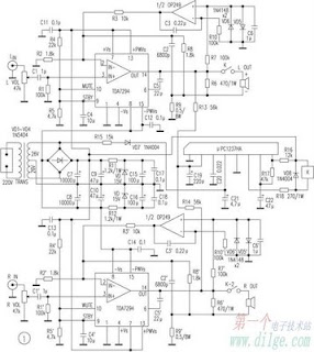
Audio power amplifier circuit 140 W
Thursday, November 20, 2014
Headphone amplifier circuit
 |
| Headphone amplifier circuit with op amp |
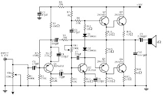
150 watts power amplifier circuit
This circuit requires only 5 pieces of transistors as the main component of reinforcement. There is no equalizer option on this amplifier circuit because it can be said of this series is very simple, so do not you compare it with that sold in the market which are usually equipped with various sound system and equalizer settings.
But to add to your collection circuit, this circuit is fairly easy and inexpensive to make and maybe one day you may need as a weak signal booster from your electronic circuit. Or you can also make this amplifier as an amplifier of high frequency signal from the output circuit animal repellent and I guarantee the results are very satisfactory.
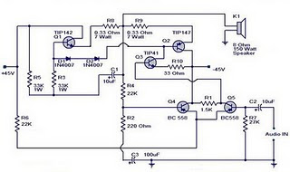
Power supply required is two-polarity power supply is + - 45 volts. Maximum power that can be obtained by this amplifier circuit is around 150 watts. As the volume control you can add potensio or variable resistor 10 Kohm in series at the input. Use dispasi loudspeaker with 150 watts power. Use a heatsink on the transistor-transistor driver loudspeaker or amplifier late as Q1 and Q2.
Monday, November 17, 2014
10W audio power amplifier with bass boost
 As the amplifier circuit also uses a number of frequencies to drive the loudspeaker, the bass frequencies will be reduced. Therefore need to be plugged the bass-boost control at fedback loop amplifier, this is done to overcome the decline in quality.
Graph bass can reach a maximum at +16.4 dB @ 50Hz.


Wednesday, November 12, 2014
25 Watt Audio Amplifier Circuit
Circuit diagram:

Parts:R1 = 47K
R2 = 4K7
R3 = 1K5
R4 = 47K
R5 = 390R
R6 = 470R
R7 = 33K
R8 = 150K
R9 = 15K
R10 = 27R
R11 = 500R-1/2W
R12 = 10R
R13 = 10R
R14 = 220R
R15 = 220R
R16 = 10R
R17 = 8.2R-2W
R18 = 22R-4W(wirewound)
C1 = 470nF-63V
C2 = 330pF-63V
C3 = 470µF-63V
C4 = 100nF-63V
C5 = 470µF-63V
C6 = 100nF-63V
C7 = 100µF-25V
C8 = 100nF-63V
C9 = 10pF-63V
C10 = 1µF-63V
C11 = 100nF-63V
Q1 = BC560C
Q2 = BC560C
Q3 = BC560C
Q4 = BC560C
Q5 = BC560C
Q6 = BD140
Q7 = BD139
Q8 = IRF530
Q9 = IRF9530
Power supply section:

Power supply circuit diagram:
Parts:R1 = 3K3-1/2W
C1 = 10nF-1000V
C2 = 4700µF-50V
C3 = 4700µF-50V
C4 = 100nF-63V
C5 = 100nF-63V
D1 = 200V 8A Diode bridge
D2 = 5mm. Red LED
F2 = 3.15A Fuses with sockets
F2 = 3.15A Fuses with sockets
T1 = 220V Primary, 25 + 25V Secondary 120VA Mains transformer
PL1 = Male Mains plug
SW1 = SPST Mains switch
Notes:
- Can be directly connected to CD players, tuners and tape recorders. Simply add a 10K Log potentiometer (dual gang for stereo) and a switch to cope with the various sources you need.
- Q6 & Q7 must have a small U-shaped heatsink.
- Q8 & Q9 must be mounted on heatsink.
- Adjust R11 to set quiescent current at 100mA (best measured with an Avo-meter connected in series to Q8 Drain) with no input signal.
- A correct grounding is very important to eliminate hum and ground loops. Connect to the same point the ground sides of R1, R4, R9, C3 to C8. Connect C11 to output ground. Then connect separately the input and output grounds to power supply ground.
- An earlier prototype of this amplifier was recently inspected and tested again after 15 years of use. Results, comments and pictures are shown here.
Sunday, November 2, 2014
100 watt Hiwatt amplifier model DR 103 power supply schematic circuit diagram
100 watt Hiwatt amplifier model DR 103 power supply schematic circuit diagram

Wednesday, October 29, 2014
TDA2050 Power Amplifier Circuit

List of components:
Resistors 1, 2, 3, 4: 22K ohm
5 resistor: 2.2 ohm
Capacitor 1: 100uF/50V
Capacitor 2: 2.2uf/50V
Capacitor 3: 22uF/50V
Capacitor 4: 0.47uF
Capacitor 5: 1000uF/50V
Capacitor 6: 100nF
Capacitor 7: 1000uF/50V
IC: TDA2050
TA8259H bassed 4 channel car amplifier Diagram Circuit
Using the TA8259H integrated circuit can be designed a very simple 4 ch BTL audio power amplifier for car audio application.
This IC can generate more high power: POUT MAX = 37 W as it is included the pure complementary PNP and NPN transistor output stage.
It is designed low distortion ratio for 4 ch BTL audio power amplifier, built-in Stand-by Function, Muting Function, Clip detector, and diagnosis circuit.
As you can see in the circuit diagram , this audio amplifier electronic project require extreme low external electronic parts .
Additionally, the AUX. amplifier is built-in, it can make the beep signal etc. output to 2 channels (OUT1 and 4).
Input voltage range that is accepted by this audio amplifier project is between 9 and 18 volt , but typically is required a 14,4 volts DC.All speakers used with this amplifier circuit project , based on TA8259H IC must have a 4 ohms impedance .
Tuesday, October 28, 2014
Mosfet High Power Amplifier complete PCB
 |
| Amplifier circuit is finished, and ready for use. |
 |
| 1000W High Power Amplifier with Mosfet Circuit Schematic Diagram |
 |
| PCB design for this Amplifier Circuit |
Simple 150 Watt Power Amplifier Circuit

Monday, October 27, 2014
Power Amplifier Protector
 |
| Power Amplifier Protector Circuits |
NCS8353 20 W stereo Class D audio amplifier Diagram Circuit
A very simple stereo Class D audio amplifier electronic circuit project can be designed using the NCS8353 audio IC capable of delivering a continuous power of up to 20 W/ch into an 8 ohms .
NCS8353 stereo Class D audio amplifier circuit is designed by ON Semiconductor and it can be powered from the existing 24 V rail in Flat Panel Television (FPTV) systems. The high efficiency of the NCS8353, 86%, reduces the requirement of an external heat sink when driving high power.
The digital power limit feature can program the output power limit at 10 W, 12 W, 15 W, or 20 W/ch, allowing the NCS8353 to be a single system solution in FPTV audio applications.
The digital power limiter quickly reduces the internal gain of the amplifier when high amplitude signals would cause excessive clipping on the output.
The gain of the NCS8353 is programmed via two gain pins, G0 and G1, allowing four selectable ranges: 20 dB, 26 dB, 32 dB, and 36 dB.
Auto recovery short circuit and over temperature protection circuitry are incorporated to ensure device functionality after short circuit and high temperature events occur .
The circuit can be powered from a wide input voltage range from 8 volt DC up to 26 volt DC .
Sunday, October 26, 2014
5000W High Power Amplifier Audio Circuits
 |
| Click To view larger | 5000W High Power Amplifier Audio Circuits Diagrams |
LA4460 Simple Audio Amplifier
 |
| LA4460 Audio Amplifier Circuit |
- work 12VDC to supply the circuit.
- Mount the LA4460 IC with an appropriate high temperature sink
- Some of as a rule worthy skin of the LA4460 IC are : reverse connection protection , muting function,thermal runaway protection circuit ,completed voltage & pitch voltage protection circuit, load stunted-circuit current limiting protection circuit, output pins DC short-circuit protection.
Friday, October 24, 2014
LM4651 and LM4652 170W power amplifier
Part of this power amplifier driver using the LM4651 IC designed specifically for the purpose of the class AB amplifier driver with short circuit protection feature, containing under voltage, thermal shutdown protection and standby functions. Section 170 Watt power amplifier using LM4651 IC with a MOSFET power amplifier is equipped with temperature sensors that will be used by IC LM4651 as controlnya thermal signal. IC IC LM4651 and LM4652 are designed specifically to each other in pairs to create a class AB power amplifier with protection features are detailed. Detailed series of 170 Watt power amplifier can be seen in thethe following figure .

Power amplifier circuit requires supply voltages +22 V DC symmetrical 0-22V. Power Amplifier with IC LM4651 and LM4652 are often used in portable HiFi systems such as powered speakers, power subwoofer and car audio power Booter. D1, D2, D3 and D4 in series 170 watt power amplifier with LM4651 and LM4652 is a 22V zener diode.
Wednesday, October 22, 2014
Splitter and Amplifier Video Circuit Diagram
Splitter and Amplifier Video Circuit Diagram
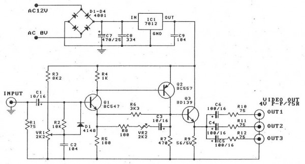
The video amplifier circuit has a maximum gain ratio of only 4 times the impedance is 75 ohms on the input and output, and wide bandwidth of this circuit is 5 Mhz
adjust VR1
1. Adjusting VR1 until the voltage at the base of Q1 is equal to one volt. And is the voltage drop across R7. (No input signal). Approximately 0.75 volts.
2. Adjust VR1 in the middle Enter the input signal is 1 Vp-p, then adjust VR2 to have the lowest rate of increase.
Then turn on the TV or monitor to the output and then adjust VR1 until the test signal to be applied without distortion.
PCB

Wednesday, October 15, 2014
4 X 15 Watt Mini Power Amplifier
Circuit diagram :
Notes :
- Assembling the circuit on a good quality PCB is a must for obtaining optimum sound quality.
- Use 12V DC for powering the circuit.
- The ICs must be fitted with adequately sized heat sinks.
- R3, R4, R12 and R13 serves as volume controllers.
- K1 to K4 can be 4 Ohm, 20W speakers.
- This amplifier circuit can be used in a variety of applications such as car audio systems, home theater systems, personal audio systems, public address systems etc.
Saturday, October 4, 2014
20W Audio Amplifier using LM1875
This is just another 20W audio amplifier circuit, but this time based on LM1875 audio amplifier IC from National Semiconductor. With a dual power supply 25V LM1875 can deliver 20W of audio power into a 4 ohm speaker. The LM1875 requires fewer external components and has a very low distortion. The IC is also filled with a number of cool features, like the upload speed fast, wide range power supply, high output current, high-swing output voltage, thermal protection, etc. The IC is available in TO -220 plastic power package and is very suitable for a variety of applications including audio systems, servo amplifiers, home theater systems, etc.
