Showing posts with label power. Show all posts

Friday, December 12, 2014

Stereo Audio Power Amplifier 20 Watt

20watt-power-amplifier

Here is a reliably high sound quality audio power amplifier project based on the National Semiconductor’s LM1875 IC.The circuit that we give is a similar form of the application circuit in the datasheet that NS provides. It is really easy to build and low cost.    
Read More..

Audio power amplifier circuit 140 W

schematic-diagram-power-amplifier


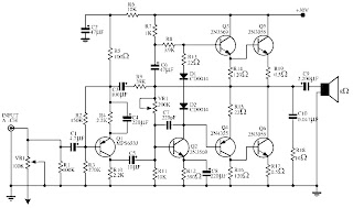
This simple schematic shows a 140W Audio power amplifier circuit by using 2N3569, 2N3055, MPS6533, 2N4355
Read More..

Thursday, November 20, 2014

150 watts power amplifier circuit

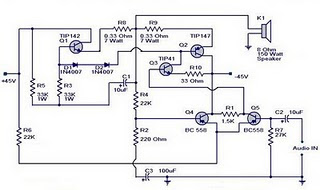
Amplifier circuit is 150 watts power amplifier circuit is quite simple.
This circuit requires only 5 pieces of transistors as the main component of reinforcement. There is no equalizer option on this amplifier circuit because it can be said of this series is very simple, so do not you compare it with that sold in the market which are usually equipped with various sound system and equalizer settings. 

But to add to your collection circuit, this circuit is fairly easy and inexpensive to make and maybe one day you may need as a weak signal booster from your electronic circuit. Or you can also make this amplifier as an amplifier of high frequency signal from the output circuit animal repellent and I guarantee the results are very satisfactory.

150


Power supply required is two-polarity power supply is + - 45 volts. Maximum power that can be obtained by this amplifier circuit is around 150 watts. As the volume control you can add potensio or variable resistor 10 Kohm in series at the input. Use dispasi loudspeaker with 150 watts power. Use a heatsink on the transistor-transistor driver loudspeaker or amplifier late as Q1 and Q2.
Read More..

Tuesday, November 18, 2014

Power Supply Variable 1 3V 12 2V 1A Circuit

Power supply circuit to generate output below were variations between 1.3V DC to 12.2V DC with 1A current. In addition, the power supply circuit is also equipped with over-current protection or shield against belebih flow. Power supply circuit is very simple, but the quality is quite good, made her basiskan regulator IC LM723 is a pretty legendary.


1.3V

Description:

R2 to set the output voltage. The maximum current is determined by R3, over-current protection circuit inside the LM723 to detect the voltage on R3, if it reaches 0.65 V, the voltage output will be off her. So the current through R3 can not exceed 0.65 / R3 although output short-circuit in his.

C3 and C4 are ceramic capacitors, as much as possible directly soldered to the PCB, this is because the LM723 is prone to oscillation that is not cool.

LM723 works with 9.5V input voltage to 40 V DC and the LM723 can generate its own current of 150mA when the output voltage is not more than 6-7V under input voltage.

Specifications:

Output (value estimated):

Vmin = (R4 + R5) / (R5 * 1.3)
Vmax = (7.15 / R5) * (R4 + R5)
Imax = 0.65/R3
Max. Power on R3: 0.42/R3
Min. DC Input Voltage (pin 12 to pin 7): Vmax + 5

Component List:

B1 40V/2.5A
C1 2200uF (3300uF even better)
C2 4.7uF
C3 100nF
C4 1NF
C5 330nF
C6 100uF
Green LED D1
D2 1N4003
F1 0.2A F
F2 2A M
IC1 LM723 (in a DIL14 plastic package)
R1 1k
R2 Pot. 5k
R3 0.56R/2W
R4 3.3k
R5 4.7k
S1 250V/1A
T1 2N3055 on a heatsink 5K / W
TR1 220V/17V/1.5
Read More..

Power supply with Z2C

Power supply with Z2C tubes are designed specifically to provide power supply voltage to the EL-34 tube amplifier push-pull in the previous article. Power supply with Z2C tube to tube power amplifier is made with a tube rectifier Z2C. Just as the power supply for power amplifier tube earlier, power supply also uses a filter 3 levels with kapsitor electrolyte. Circuit power supply with tube rectifier Z2C can give +210 VDC output voltage. A complete range of power supply for power amplifier tube can be seen in thethe following figure .

Power


Z2C on the rectifier tube in power supply with tube above require a supply voltage for the filaments taken from the other side of the transformer secondary. Power supply with Z2C tube is a power supply that dapt used as a substitute power supply for power amplifier tubes with a diode in previous articles.
Read More..

Monday, November 17, 2014

6 to 12 Volt Power Supply Inverter

This inverter circuit can provide up to 800mA of 12V power from a 6V supply. For example, you could run 12V car accessories in a 6V (British?) car. The circuit is simple, about 75% efficient and quite useful. By changing just a few components, you can also modify it for different voltages.


6
Part List:

R1, R4 2.2K 1/4W Resistor
R2, R3 4.7K 1/4W Resistor
R5 1K 1/4W Resistor
R6 1.5K 1/4W Resistor
R7 33K 1/4W Resistor
R8 10K 1/4W Resistor
C1,C2 0.1uF Ceramic Disc Capacitor
C3 470uF 25V Electrolytic Capcitor
D1 1N914 Diode
D2 1N4004 Diode
D3 12V 400mW Zener Diode
Q1, Q2, Q4 BC547 NPN Transistor
Q3 BD679 NPN Transistor
L1 See Notes
MISC Heatsink For Q3, Binding Posts (For Input/Output), Wire, Board
Read More..

10W audio power amplifier with bass boost


As the amplifier circuit also uses a number of frequencies to drive the loudspeaker, the bass frequencies will be reduced. Therefore need to be plugged the bass-boost control at fedback loop amplifier, this is done to overcome the decline in quality.


Graph bass can reach a maximum at +16.4 dB @ 50Hz.
This circuit can be connected directly to the CD player, tuner, and tape recorders. Q3 and Q4 must be in pairs with a heatsink.

Adjust the volume control at minimum position and R3 with a minimum value of resistance as well. try enabling circuit R3 da set up to read the flow of about 20 to 25mA. Wait for 15 minutes, connect the ground at J1, P1, C2, C4 C3dan. Connect also C9 at the output ground.


For his series of power supply you can use the following scheme that fits perfectly with this amplifier.


Read More..

Power supply with driver TEA1507

Power supply with driver TEA1507 is mostly used by TV branded PHILIPS. Power Supply has an efficiency rate of up to 90% - thus requiring less cooling, as well as stand-by power required is less than 1 watt.

Power Supply with TEA driver is equipped with a variety of surge protector that has a high reliability - not easily damaged if any part of a damaged power supply circuit and power transistor or FET heat is not easily damaged. Power supply circuits are dapatapat working on ac input voltage between 85 up to 275v. The way it works with the driver circuit power supply TEA 1507 is quite simple, so easy tracking of damage to the circuit.


The picture above is the basic power supply circuit with TEA1507
Read More..

Sunday, November 9, 2014

Automatic Low Power Emergancy Light

Here is a white-LED-based emergency light that offers the following advantages. 1-It is highly bright due to the use of white LEDs. 2-The light turns on automatically when mains supply fails, and turns off when mains power resumes. 3-It has its own battery charger. When the battery is fully charged, charging stops automatically. The charger power supply section is built around 3-terminal adjustable regulator IC LM317 (IC1), while the LED driver section is built around transistor BD140 (Q2).

In the charger power supply section, an input AC main is stepped down by T1 to deliver 9V, 500mA to the bridge rectifier, which comprises diodes D1 through D4. Filter capacitor C1 eliminates ripples. Unregulated DC voltage is fed to input pin 3 of IC1 and provides charging current through D5 and limiting resistor R15. By adjusting preset P1, the output voltage can be adjusted to deliver the required charging current. When the battery gets charged to 6.8V, D6 conducts and charging current from IC1 finds a path throughQT1 to ground and it stops charging of the battery. When mains power is available, the base of Q2 remains high and Q2 does not conduct. Thus LEDs are off.

On the other hand, when mains fails, the base of Q2 becomes low and it conducts. This makes all the LEDs glow. The mains power supply, when available, charges the battery and keeps the LEDs off as Q2 remains cut-off. During mains failure, the charging section stops working and the B1 supply makes the LEDs glow. Assemble the circuit on a general-purpose PCB and enclose in a cabinet with enough space for battery and switches. We have tested the circuit with twelve 10mm white LEDs. You can use more LEDs provided the total current consumption does not exceed 1.5A. Driver transistor Q2 can deliver up to 1.5A with proper heat-sink arrangement.

Circuit diagram:

Fully Automatic Emergency Light Circuit Diagram
Parts:

P1 = 2.2K
R1-R12 = 100R-1/2W
R13 = 1K-1/2W
R14 = 180R-1/2W
R15 = 16R/5W
R16 = 1.2K
C1 = 1000uF-25V
D1-D5 = 1N4007
D6 = 6.8V-0.5W Zener
D7-D18 = 10mm- White LEDs
Q1 = BC548
Q2 = BD140
B1 = 6V-4.5Ah Battery
IC1 = LM317
T1 = 9Vac-Transformer
Read More..

Friday, November 7, 2014

Power On Indicator

Some types of electronic equipment do  not provide any indication that they are  actually on when they are switched on.  This situation can occur when the back-light of a display is switched off. In addition, the otherwise mandatory mains  power  indicator  is  not  required  with  equipment  that  consumes  less  than  10 watts. As a result, you can easily forget  to switch off such equipment. If you want  to know whether equipment is still drawing power from the mains, or if you want  to have an indication that the equipment  is switched on without having to modify the equipment, this circuit provides a solution. 

image

One way to detect AC power current and  generate a reasonably constant voltage  independent of the load is to connect a  string of diodes wired in reverse parallel in series with one of the AC supply  leads. Here we selected diodes rated  at 6 A that can handle a non-repetitive  peak current of 200 A. The peak current  rating is important in connection with  switch-on  currents.  An  advantage  of  the selected diodes is that their voltage  drop increases at high currents (to 1.2 V  at 6 A). This means that you can roughly  estimate the power consumption from  the brightness of the LED (at very low  power levels). The voltage across the diodes serves as  the supply voltage for the LED driver. To  increase the sensitivity of the circuit, a  cascade circuit (voltage doubler) consisting of C1, D7, D8 and C2 is used to double  the voltage from D1–D6. Another benefit  of this arrangement is that both halve- waves of the AC current are used. We use  Schottky diodes in the cascade circuit to  minimise the voltage losses.
Circuit diagram :
Power On Indicator Circuit Diagram
 
The LED driver is designed to operate the LED  in blinking mode. This increases the amount  of current that can flow though the LED when  it is on, so the brightness is adequate even  with small loads. We chose a duty cycle of pproximately 5 seconds off and 0.5 second  on. If we assume a current of 2 mA for good  brightness with a low-current LED and we can  tolerate a 1-V drop in the supply voltage, the  smoothing capacitor (C2) must have a value of  1000 µF. We use an astable multivibrator built around two transistors to implement a  high-efficiency LED flasher. It is dimensioned to minimise the drive current of  the transistors. The average current consumption is approximately 0.5 mA with a  supply voltage of 3 V (2.7 mA when the  LED is on; 0.2 mA when it is off). C4 and  R4 determine the on time of the LED (0.5  to 0.6 s, depending on the supply volt-age). The LED off time is determined by  C3 and R3 and is slightly less than 5 seconds. The theoretical value is R × C × ln2,  but the actual value differs slightly due to  the low supply voltage and the selected  component values.
 
Diodes D1-D6 do not have to be special  high-voltage diodes; the reverse volt-age is only a couple of volts here due  the reverse-parallel arrangement. This  voltage drop is negligible compared to  the value of the mains voltage. The only  thing you have to pay attention to is the  maximum load. Diodes with a higher  current rating must be used above 1 kW.  In addition, the diodes may require cool-ing at such high power levels.  Measurements on D1–D6 indicate that  the voltage drop across each diode is  approximately 0.4 V at a current of 1 mA.  Our aim was to have the circuit give a  reasonable indication at current levels  of 1 mA and higher, and we succeeded  nicely. However, it is essential to use a  good low-current LED.
 
Caution: the entire circuit is at AC power potential. Never work on the circuit with the mains cable plugged in. The  best enclosure for the circuit is a small,  translucent box with the same colour as  the LED. Use reliable strain reliefs for the  mains cables entering and leaving the  box (connected to a junction box, for  example). The LED insulation does not  meet the requirements of any defined insulation class, so it must be fitted such that it  cannot be touched, which means it cannot  protrude from the enclosure.
Read More..

LM317 variable power supply

A truly timeless circuit. LM317 is a versatile and highly efficient 1.2-37V voltage regulator that can provide up to 1.5A of current with a large heat sink. Its ideal for just about any application. This was my first workbench power supply and I still use it.

 LM317 variable power supply Circuit Diagram


 lm317 variable power supply circuit diagram

Since LM317 is protected against short-circuit, no fuse is necessary. Thanks to automatic thermal shutdown, it will turn off if heating excessively. All in all, a very powerful (and affordable!) package, indeed.

Although LM317 is capable of delivering up to 37V, the circuit pictured here is limited to 25V for the sake of safety and simplicity. Any higher output voltage would require additional components and a larger heat sink.

Make sure that the input voltage is at least a couple of Volts higher than the desired output. Its ok to use a trimmer if youre building a fixed-voltage supply.Problems:Follow all the safety precautions when working with mains voltage. Insulate all connections on the transformer.

Possible uses:Variable workbench power supply, fixed-voltage supply... Just about any possible application when no more than 1.5A is necessary.
Read More..

Thursday, November 6, 2014

Low Cost Power Buzzer

How often on average do you have to call members of your family each day to tell them that dinner is ready, it’s time to leave, and the like? The person you want is usually in a different room, such as the hobby room or bedroom. A powerful buzzer in the room, combined with a push button at the bottom of the stairs or in the kitchen, could be very handy in such situations.

 The heart of this circuit is formed by IC1, a TDA2030. This IC has built-in thermal protection, so it’s not likely to quickly give up the ghost. R1 and R2 apply a voltage equal to half the supply voltage to the plus input of the opamp. R3 provides positive feedback. Finally, the combination of C2, R4 and trimmer P12 determines the oscillation frequency of the circuit.

Power Buzzer Circuit Diagram:
 power buzzer circuit diagram

The frequency of the tone can also be adjusted using P1. There is no volume control, since you always want to get attention when you press pushbutton S1. Fit the entire circuit where you want to have the pushbutton. The loudspeaker can then be placed in a strategic location, such as in the bedroom or wherever is appropriate. Use speaker cable to connect the loudspeaker. Normal bell wire can cause a significant power loss if the loudspeaker is relatively far away. The loudspeaker must be able to handle a continuous power of at least 6 W (with a 20-V supply voltage).

The power quickly drops as the supply voltage decreases (P = Urms 2 / RL). The power supply for this circuit is not particularly critical. However, it must be able to provide sufficient current. A good nominal value is around 400 mA at 20 V. At 4 V, it will be approximately 25 mA. Most likely, you can find a suitable power supply somewhere in your hobby room. Otherwise, you can certainly find a low-cost power supply design in our circuits archive that will fill the bill!

Read More..

Tuesday, November 4, 2014

Non Contact Power Monitor

Here is a simple non-contact AC power monitor for home appliances and laboratory equipment that should remain continuously switched-on. A fuse failure or power breakdown in the equipment going unnoticed may cause irreparable loss. The monitor sounds an alarm on detecting power failure to the equipment. The circuit is built around CMOS IC CD4011 utilising only a few components. NAND gates N1 and N2 of the IC are wired as an oscillator that drives a piezobuzzer directly. Resistors R2 and R3 and capacitor C2 are the oscillator components. The amplifier comprising transistors T1 and T2 disables the oscillator when mains power is available. In the standby mode, the base of T1 picks up 50Hz mains hum during the positive half cycles of AC and T1 conducts.

Non-Contact Power Monitor Circuit diagram:
    Power

This provides base current to T2 and it also conducts, pulling the collector to ground potential. As the collectors of T1 and T2 are connected to pin 2 of NAND gate N1 of the oscillator, the oscillator gets disabled when the transistors conduct. Capacitor C1 prevents rise of the collector voltage of T2 again during the negative half cycles. When the power fails, the electrical field around the equipment’s wiring ceases and T1 and T2 turn off. Capacitor C1 starts charging via R1 and preset VR and when it gets sufficiently charged, the oscillator is enabled and the piezobuzzer produces a shrill tone. Resistor R1 protects T2 from short circuit if VR is adjusted to zero resistance.

The circuit can be easily assembled on a perforated/breadboard. Use a small plastic case to enclose the circuit and a telescopic antenna as aerial. A 9V battery can be used to power the circuit. Since the circuit draws only a few microamperes current in the standby mode, the battery will last several months. After assembling the circuit, take the aerial near the mains cable and adjust VR until the alarm stops to indicate the standby mode. The circuit can be placed on the equipment to be monitored close to the mains cable.


Read More..

Sunday, November 2, 2014

PRECISION POWER REGULATOR ELECTRONIC DIAGRAM


PRECISION POWER REGULATOR ELECTRONIC DIAGRAM

A precision voltage source is quite easy, except when the voltage should be consistent over wide range of ambient temperature. This requirement might be needed in high precision measurement system environment. For example, to provide reference voltage in analog to digital conversion.
Read More..

100 watt Hiwatt amplifier model DR 103 power supply schematic circuit diagram

Description :
100 watt Hiwatt amplifier model DR 103 power supply schematic circuit diagram
Read More..

Wednesday, October 29, 2014

TDA2050 Power Amplifier Circuit

High output power, low distortion, power amp for HiFi and high class TV sets. Maximum output at 4 ohm speaker is 35 watts, while the 8 ohm speaker is only 15 watts. This circuit must use a good power supply so that the sound quality could be as expected.

TDA2050

List of components:
     Resistors 1, 2, 3, 4: 22K ohm
     5 resistor: 2.2 ohm
     Capacitor 1: 100uF/50V
     Capacitor 2: 2.2uf/50V
     Capacitor 3: 22uF/50V
     Capacitor 4: 0.47uF
     Capacitor 5: 1000uF/50V
     Capacitor 6: 100nF
     Capacitor 7: 1000uF/50V
     IC: TDA2050
Read More..

Tuesday, October 28, 2014

Mosfet High Power Amplifier complete PCB

Amplifier
Amplifier circuit is finished, and ready for use.
1000W High Power Amplifier MOSFET LEGEND stage Master MK2 is a very high-quality and powerful amplifier. It is not into the classroom HiEnd for sure, but very respectable sounding element with lots of of power. It was not designed with national interior because the primary goal already, such a power used barely rarely at home the board and interior with the exception of perhaps in a few superior nightclubs. Frankly, due to a tall performance, may possibly helper light to a certain extent proceed categorize, but other specifications and significant quality on the supporter values and needs! My no more than other submission meant for you to think approaching it on extent, Master internship in the role of a Master MK2. Internship Master 500…1000W, but is a a tiny easier (and cheaper) to build. ” PCB present in this fashion as beneath 1000W Mosfet PCB 1000W mosfet PCB.

1000W
1000W High Power Amplifier with Mosfet Circuit Schematic Diagram
Printed
PCB design for this Amplifier Circuit
Read More..

Simple 150 Watt Power Amplifier Circuit

This is the very simple circuit diagram of 150W power amplifier. The circuit is easy enough to built without PCB. The power output range is about 100-150W depends to the power supply and the Darlington’s you use for the amplifier. Heatsink is a must since the final transistor is going to hot when the amplifier is activated.

Simple


The amplifier requires split power supply. The transformer is depending to your home electrical installation, it can be 110V or 220V primary. Use 35V-0-35V secondary (transformer output), you will get about 45V DC output from transformer 35V AC after rectified by the diodes. The Transformer current output should be at least 4A for better audio performance. Use 4A / 100V diodes.
Read More..

Monday, October 27, 2014

Power Amplifier Protector

Now you can protect your HiFi amplifier from damage due to overheating. This circuit will cut off power to the amplifier board at the time the temperature was high. Automatically connect the power when the temperature returns to normal. This circuit uses a sensor NTC Thermister heat and also has a warning sound and reset determination.

Amplifier circuit protector is using popular timer IC NE 555 as the temperature controlled switch. The trigger pin 2 is connected to a potential divider consisting Thermister VR and NTC. Thus the voltage on pin 2 depending on the resilience and determination Thermister VR. NTC (Negative Temperature Coefficient) Thermister has a high resistance in the normal temperature and the resistance decreases as temperature increases. Threshold pin 6 of IC is used to reset the IC if necessary. When the pin 6 voltage gets higher than the IC pin 2 will reset and the output is low.

Power Amplifier Protector  Circuits

Power to the amplifier board is given by (NC) contact is usually connected from the relay and the switch S2. So that power to the amplifier board will be available through the NC contacts of the relay when the relay S2 and the state is not powered. Thermister resistance is governed by VR triggering pin 2 of IC peaks at normal temperatures. When the temperature inside the cabinet amplifier increases, resistance decreases so that it becomes conductive Thermister. This makes the trigger pin 2 of IC is low and its output is high. T1 works so that the relay energizes and the ringing of a bell. This will damage the electrical supply to the amplifier board. Relay will not be automatically powered when the temperature returns to normal.

Amplifier circuit protectors are very useful to protect your home sound system.
Read More..

Sunday, October 26, 2014

5000W High Power Amplifier Audio Circuits

The High Power Amplifier has great advantages are 5000W ultra-light, high-power audio amplifier, without switching-mode power supply. This ambit is of an 2 x 2,500W RMS Stereo amplifier, super-light and after switching-mode ability supply. The ambit aloof shows a channel, and the ability accumulation that it assists to the two channels. The audio ambit should be duplicated, but the ability accumulation assists to the two channels after problems.

Click To view larger | 5000W High Power Amplifier Audio Circuits Diagrams

A adapted affliction should be destined to the careful agent of the audio line, that should be of audio-high-quality, of the blazon acclimated in microphone pre amps ascribe line. The accomplished accumulation (2 channels) of 5,000W RMS it should not counterbalance added than 32 lbs, already central of an adapted brownish box.

WARNING:
This ambit is alone for abecedarian use. It contains not-isolated genitalia of the electric AC net and it can be actual dangerous. The access for the speakers are not abandoned of the calm AC net and it requests added care. This action seeks to acting a accepted ability accumulation with abundant weight and amount reduction, after necessarily to use a switching-mode ability supply.

This action cannot be accustomed in some countries for commercial-use. The columnist doesn’t accept any albatross for the anatomy as that ambit it will be applied.
Read More..