Friday, December 12, 2014
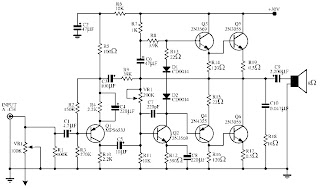
Audio power amplifier circuit 140 W

Monday, October 27, 2014
NCS8353 20 W stereo Class D audio amplifier Diagram Circuit
A very simple stereo Class D audio amplifier electronic circuit project can be designed using the NCS8353 audio IC capable of delivering a continuous power of up to 20 W/ch into an 8 ohms .
NCS8353 stereo Class D audio amplifier circuit is designed by ON Semiconductor and it can be powered from the existing 24 V rail in Flat Panel Television (FPTV) systems. The high efficiency of the NCS8353, 86%, reduces the requirement of an external heat sink when driving high power.
The digital power limit feature can program the output power limit at 10 W, 12 W, 15 W, or 20 W/ch, allowing the NCS8353 to be a single system solution in FPTV audio applications.
The digital power limiter quickly reduces the internal gain of the amplifier when high amplitude signals would cause excessive clipping on the output.
The gain of the NCS8353 is programmed via two gain pins, G0 and G1, allowing four selectable ranges: 20 dB, 26 dB, 32 dB, and 36 dB.
Auto recovery short circuit and over temperature protection circuitry are incorporated to ensure device functionality after short circuit and high temperature events occur .
The circuit can be powered from a wide input voltage range from 8 volt DC up to 26 volt DC .
Thursday, September 18, 2014
4 x 45 W power amplifier
- I2C-bus control
- Hardware programmable I2C-bus address
- Can drive a 2 Ω load with a battery voltage of up to 16 V and a 4 Ω load with a battery voltage of up to 18 V
- DC-load detection: open, short and present
- AC-load (tweeter) detection
- Programmable clip detection: 1 % or 3 %
- Programmable thermal protection pre-warning
- Independent short-circuit protection per channel
- Low gain line driver mode (20 dB)
- Loss-of-ground and open VP safe
- All outputs protected from short-circuit to ground, to VP, or across the load
- All pins protected from short-circuit to ground
- Soft thermal clipping to prevent audio holes
- Low battery detection.
 |
| Circuit diagram for TDA8593 |
 |
| PCB layout of test and application circuit; components bottom |
 |
| PCB layout of test and application circuit; copper layer bottom |
 |
| PCB layout of test and application circuit; components top |
 |
| PCB layout of test and application circuit; copper layer top |
Saturday, September 6, 2014
Car Amplifier Circuit 2 x 30 W stereo
This circuit use the IC AN7166 . On circuit have an advantage is very loud sound , although only 30W this circuit is like a 100 W transistor power amplifier. Its so good circuit with IC AN7166 . This circuit require minimum voltage 12 V and Maximum voltage 24 volt , I recomended voltage for this circuit is 18 volt. And use the battery supply current 5 Ampere. Maximum power output of one speaker 30 W with impedance 4 Ohm.
See this circuit schematic below :
 |
| Click image to view large |
Capacitor thats connect legs IC 4 and 3 is 1 nF . And capacitor thats connect legs IC 9 and 3 is 1 nF. For the input capacitor at 1 uF ( L and R ) for output capacitor at 1000uF with voltage 50 V or higher.
Thursday, September 4, 2014
LM 386 Amplifier circuit 1 W
LM 386 general description:
LM 386 circuit diagram:

LM 386 partlist:
R1 = 10 kR 2 = 10 Ω
P1 = 10 k
C1 = 100 nF
C2 = 47 nF
C3 = 470 uF
C4 = 10 uF
C5 = 33 nF
IC1 = LM 386
S1 = switch
