Showing posts with label the. Show all posts
Showing posts with label the. Show all posts
Thursday, November 20, 2014
Basically the DAC circuit
Basically the DAC circuit is made to meet the need for the level of influence in the development of digital electronic circuits electronics world.
Since the discovery of Silicon and Germanium semiconductor material then quickly there was a revolution in terms of simplicity and accuracy of an electronic circuit. Besides, with the implementation of digital circuits will support at all in terms of data storage and mobility. Lots of data can now be operated with a computer is a data converted from analog signals. For example a voice signal or analog form of video can be played and stored using a computer after analog signals are converted into digital data.
 Advantages possessed by the digital data than analog signal is a certainty the nature of the data or logic. Digital data only can be divided into two kinds of logic high "1" and logic low "0". Logic 1 represents 5 volts and low logic voltage 0 volts represents. Examples of the advantages of digital signals over analog signals is on television or digital radio receiver. By implementing a digital system signals emitted by television or radio stations will form the data 1 and 0, so at the time of the transmission or delivery of data signals that change or damaged by the interruption of transmission will hardly change the logic of the signals. But if the transmitted signal is the original signal in the form of an analog signal then if just a little damage due to interruption of transmission, the signal to be received is a signal that has been damaged serve targeted.
In the DAC circuit above uses two LM741 Op-Amp IC is often used as an amplifier. IC1 to function as a producer of analog signal is reversed, and turned back IC2 function signal from IC1. Basic circuit of the DAC is a common amplifier circuit, only used a variation of several resistors in order to obtain a regular reinforcement signal. Rules that must be understood from this DAC circuit is the value of resistors on the input op-amp. The value for the resistor at high bit (R4) should be 2x the amplifier resistor (R5), then for the next bit should be 2x the resistor value at a higher bit. So if the circuit uses 4-bit DAC is the unit bit (lowest bit) is the value of bits to be 8x-4. From the picture above the unit bit is represented by resistor 80 Kohm.
Sample Conditions:
- 0001 (1) = switch SW1 closed and others opened, the voltage output produced is (5K/80K) x 9 volt = 0.5625 volts
- 0010 (2) = SW2 is closed and another switch is opened, the output voltage is (5K/40K) x 9 volts = 1.125 volts
- 0011 (3) = SW1 and SW2 is closed and another switch is opened, the voltage output is (5K/Rparalel 80K and 40K) x 9 volt = (5K/26, 667K) X 9 volt = 1.6875 volts
- 1000 (8) = SW4 is closed and another switch is opened, the output voltage is (5K/10K) x 9 volts = 4.5 volts.
From the above calculation can be concluded that unlicensed with a voltage output proportional to the input conditions, eg for 1 decimal is 0.5625 volts then, decimal 2 = 2 x 0.5625 = 1125 volts, decimal 3 = 3 x 0.5625 = 1.6875 volts, and so on. This condition is due to the parallel relationship between the input resistors.
Read More..
Since the discovery of Silicon and Germanium semiconductor material then quickly there was a revolution in terms of simplicity and accuracy of an electronic circuit. Besides, with the implementation of digital circuits will support at all in terms of data storage and mobility. Lots of data can now be operated with a computer is a data converted from analog signals. For example a voice signal or analog form of video can be played and stored using a computer after analog signals are converted into digital data.
In the DAC circuit above uses two LM741 Op-Amp IC is often used as an amplifier. IC1 to function as a producer of analog signal is reversed, and turned back IC2 function signal from IC1. Basic circuit of the DAC is a common amplifier circuit, only used a variation of several resistors in order to obtain a regular reinforcement signal. Rules that must be understood from this DAC circuit is the value of resistors on the input op-amp. The value for the resistor at high bit (R4) should be 2x the amplifier resistor (R5), then for the next bit should be 2x the resistor value at a higher bit. So if the circuit uses 4-bit DAC is the unit bit (lowest bit) is the value of bits to be 8x-4. From the picture above the unit bit is represented by resistor 80 Kohm.
Sample Conditions:
- 0001 (1) = switch SW1 closed and others opened, the voltage output produced is (5K/80K) x 9 volt = 0.5625 volts
- 0010 (2) = SW2 is closed and another switch is opened, the output voltage is (5K/40K) x 9 volts = 1.125 volts
- 0011 (3) = SW1 and SW2 is closed and another switch is opened, the voltage output is (5K/Rparalel 80K and 40K) x 9 volt = (5K/26, 667K) X 9 volt = 1.6875 volts
- 1000 (8) = SW4 is closed and another switch is opened, the output voltage is (5K/10K) x 9 volts = 4.5 volts.
From the above calculation can be concluded that unlicensed with a voltage output proportional to the input conditions, eg for 1 decimal is 0.5625 volts then, decimal 2 = 2 x 0.5625 = 1125 volts, decimal 3 = 3 x 0.5625 = 1.6875 volts, and so on. This condition is due to the parallel relationship between the input resistors.

Friday, October 31, 2014
Universal Battery Charger Battery charger for general purpose usage Universal Battery Charger circuit diagram The chargers output voltage is adjust
Universal Battery Charger

Power transistors Q1 and Q2 are connected as series regulators to control the battery chargers output voltage and charge-current rate. An LM-317 adjustable voltage regulator supplies the drive signal to the bases of power transistor Q1 and Q2. Potensiometer R9 sets the output-voltage level. A current sampling resistor, R8 (a 0.1 ohm/5W unit), is connected between the negative output lead and circuit ground. For each amp of charging current that flows through R8, a 100mV output is developed across it. The voltage developed across R8 is fed to one input of comparator U3. The other input of the comparator is connected to variable resistor R10.
As the charging voltage across the battery begins to drop, the current through R8 decrease. Then the voltage feeding pin 5 of U3 decreases, and the comparator output follows, turning Q3 back off, which completes the signals circular path to regulate the batterys charging current.
The charging current can be set by adjusting R10 for the desired current. The circuits output voltage is set by R9
Thursday, October 30, 2014
Subwoofers are the quality car sound
 Car subwoofers are the life of a quality car sound organization. Basically, subwoofers are nothing supplementary than bonus speakers attached to your sound system. Car subwoofers might be situated passive otherwise powered. Passive woofers obtain their power from the cars audio arrangement, but a powered subwoofer derives its power independently. These days, indoors keeping with the newest technologies, car subwoofers draw closer in all shapes, sizes and flag.
 being you could know, altered speakers attached to amplifiers hand over different frequencies of sounds. Subwoofers attached to an amplifier deliver low frequency low sounds in the song. In usual sound systems, the octaves are missing. in the main, listeners puzzle out not yearn for these sounds either. But if you fancy the rich and varied sounds of harmony, before if you covet to listen in to deep tracks (composition with the aim of has been personally formed instead of low), you would miss subwoofers willfully. Car subwoofers are a should if you want the car to echo with the beat of your melody.
round about of the paramount car subwoofers include Sony, Alpine and Kenwood. both of these products is well priced and delivers sharp quality sound. However, carry out run a voice check or you try ready slightly of these subwoofers since except the subwoofer delivers deep sounds, you might when well try with no them. You in addition need a subwoofer procedure with the purpose of good wishes the be and day of your vehicle.
Car subwoofers might range from 8 inches to 60 inches. nearly everyone subs are mounted clothed in boxes. But these days you can and urge them in a tube mounted format. usually, the subwoofer choice give rise to the amplifier connected to it so in the same way as to help it give the vital sound. Since power supplies are quite above what is usual in subwoofers and since you need accurate power supply to deliver high quality sounds, an amplifier is pretty much a obligation on behalf of subwoofers.
While business your car subwoofer, the key phenomenon you have to decide is everyplace to obtain it from. A integer of selections are open online, and a allocation of them are competitively priced. But, make it a aim to buy from apparent online dealers. after that, decide on the funds. Subwoofers are a luxury; they greet rations with the purpose of are ended and exceeding common expectations. So, solve not try to scrimp and save. lead to on behalf of the paramount quality subwoofers your financial statement desire allow. Longevity and quality matters. If you cannot afford regular prices, try not on online auctions. You can bag selected real bargains on time. then again, you could in addition consider exchange quality subwoofers with the aim of be inflicted with been used, but are inwards sound condition. A miniature caution and sensible selection spirit assent to you have a sound arrangement with the intention of is next to nothing.
Ask a few car audiophile, and they will acquaint with you that you simply cannot make with a car subwoofer. a long time ago you catch hooked to the pleasure of listening to right, extraordinary quality sound, you would remain singing the same pitch (excuse the pun).
7 Elephants has been a main distributor of many brands of car audio equipment such in the role of Pioneer, Kenwood, JVC, Sony, Panasonic and extra on reasonable prices.
Wednesday, October 29, 2014
LG Gx2 5 7 inch cell with the same laser technology in LG Camera G3
LG is presenting streak new cell before IFA 2014 Earlier this week the company introduced the LG Stylus G3 to challenge the Samsung Galaxy Note, but apparently thats not all you have prepared and presented the LG Gx2, which can be easily confused with the LG G2x years ago.
The new LG cell Gx2 also wants to enter the territory of the Samsung Galaxy Note to have a 5.7 inch screen, but its specifications are still being average and not high end.
Gx2 LG screen has a resolution HD (720p), a quad-core 1.2GHz processor, 1.5GB of RAM and 8GB of storage.
Additionally, the cell has a ATTERY of 3,200mAh, a rear 8 megapixel camera, 1.3 megapixel front camera and battery 3,200mAh. The rear camera has the same technology found in the LG G3, mainly the laser autofocus.
LG has not announced when it would be released in that country and what would be its price. However, there is the possibility that, for the moment, leave only in Asia, but do not rule out the possibility of reaching other markets in the future.
The new LG cell Gx2 also wants to enter the territory of the Samsung Galaxy Note to have a 5.7 inch screen, but its specifications are still being average and not high end.
Gx2 LG screen has a resolution HD (720p), a quad-core 1.2GHz processor, 1.5GB of RAM and 8GB of storage.
Additionally, the cell has a ATTERY of 3,200mAh, a rear 8 megapixel camera, 1.3 megapixel front camera and battery 3,200mAh. The rear camera has the same technology found in the LG G3, mainly the laser autofocus.
LG has not announced when it would be released in that country and what would be its price. However, there is the possibility that, for the moment, leave only in Asia, but do not rule out the possibility of reaching other markets in the future.
Thursday, October 23, 2014
Make a series letters from the LED
Make a series letters from the LED , Things to consider before making the sign of the LED array,
1) Use LED nodes.
2) Paint the top of the PCB with a dark color (black).
3) Note the LED specifications. In this experiment use a 5mm diameter LED nodes
that emit red, specification voltage of 3 volts.
The assembly of LED:
1) One letter composed at most 5 columns and 7 rows.
2) One column mostly composed by 6 LEDs are arranged series.
3) Then the fifth column are connected in parallel.
Here is one letter LED scheme.
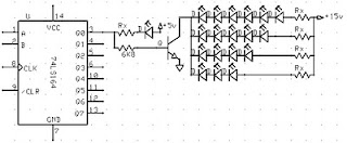
Medium picture below is the lay out of the 2-letter nameplate. To make the sign 8 letter, copied from a second stay this letter.

Example of LED on the letters A and B:

Read More..
1) Use LED nodes.
2) Paint the top of the PCB with a dark color (black).
3) Note the LED specifications. In this experiment use a 5mm diameter LED nodes
that emit red, specification voltage of 3 volts.
The assembly of LED:
1) One letter composed at most 5 columns and 7 rows.
2) One column mostly composed by 6 LEDs are arranged series.
3) Then the fifth column are connected in parallel.
4) Each column given the constraints, Rx, which amount depends on the number of LEDs in one column and depends also on the type of LED (in this experiment that used LED 5mm in diameter, clear with red light beam).
5) In a column consisting of 6 LEDs, Rx = 330 ohm, 5 LEDs, Rx = 560 Ohms, 4 LEDs, Rx = 680 Ohms Remember, this provision applies to 5 mm LED red light beam nodes.
6) Every letter was given FCS9013 transistor amplifier. Here is one letter LED scheme.

Medium picture below is the lay out of the 2-letter nameplate. To make the sign 8 letter, copied from a second stay this letter.

Example of LED on the letters A and B:
Value Rx in the first and the fifth column (letter A) of 560 ohms, because it consists of 5 LEDs are arranged series. Rx in the second column, third, and fourth, amounting to 680 ohms because it consists of two LEDs.
Rx first column letter B, 330 ohms. Rx second column, third, fourth, and fifth at 680 ohms.Thursday, September 18, 2014
The Audio Video Distribution Amplifier
With the amount of equipment in home entertainment centers today the need to be able to vary the gain of the audio or video signal is needed. I found this particular circuit helpful when used in conjunction with the Universal Descrambler and a Stabilizer circuit I built for making copies of video tapes. It not only allowed me the ability to fine tune the video strength it also helped me increase the recorded audio which typically becomes poor when making tape copies. Circuit operation is straight forward for amplifier circuits. The second channel for the audio amplifier is made up of the same components except the other half of IC1 is used. Pin 6 & 5 are inputs and 7 is the output.
Circuit Diagram


Circuit Diagram


Wednesday, September 10, 2014
Signal strength indicator on the 64 LEDs
I present to you a simple project indicator audio signal, a distinctive feature of this project from others is that in the scheme for each channel I primel 32 LEDs to get the long line. At the heart device - AVR microcontroller Atmel ATmega8535, ULN2803 - 8-channel key Darlington, moreover, operational amplifiers, his appointment think its also clear. Sensitivity indicator is adjusted by resistors R32 and R33, for each channel separately. This project is my thesis work I did a couple of years ago, when the scheme came across sharilsya in folders on your PC, and decided to send to the site.
The scheme is quite large, reduce LED designation did not, the scheme can be found below:


The entire device is going on a breadboard, PCB did not draw who liked the project can draw the circuit board and send it to the forum. All radio components in the circuit can be replaced by a similar, resistor and capacitor can be placed close to par. The transistors may be replaced by any other similar. Crystal oscillator can be put on 14-16 MHz, is not critical. Photos of the device below:
.jpg)
When programming the microcontroller does not need to put fuse bits, ie we select the desired controller in the program, open firmware and click flash. If the device is assembled correctly, the circuit work immediately.
Original article sourse cxem.netMonday, September 1, 2014
Canon EOS M Digital Camera Enters into the Mirrorless Territory
Canon has long been a leader in the world of DSLRs, but when it comes to smaller sized shooters, Canon had largely concentrated on commercially viable consumer and prosumer class digital cameras, not really treading on the mirrorless camera technology known as Micro Four Thirds which has been around for some years now. The mirrorless camera comes close to a DSLR in terms of image quality, and yet is far less bulkier in terms of size, not to mention allowing you to change a fair number of lenses (a market which is growing), making it a favorite secondary camera to many.
Well, Canon has finally decided to dip their toes into this particular market, by offering the Canon EOS M digital camera which is said to deliver exceptional EOS Full HD video quality with continuous autofocus, not to mention having it accompanied by a notable and expansive range of lenses.
Inspired by EOS technology, the EOS M will be able to leverage on the company’s core technologies, while distilling them down in order to deliver outstanding video capture capabilities without sacrificing image quality when it comes to still shots. Whenever you want to capture still images, the EOS M camera’s 18-megapixel APS-C-sized CMOS image sensor is more than capable of delivering a shallow depth of field, in addition to incredible low-light image quality and a wide dynamic range which is more than capable of capturing rich gradation and detail.
This is the latest member of the EOS family, where both videographers and photographers alike regardless of their level of professionalism and interest, will be able to play nice with a couple of lenses that were specially designed for Canon’s new camera format – namely the EF-M 22mm f/2 STM kit lens and the optional EF-M 18-55mm f/3.5-5.6 IS STM lens. Not only that, you are also able to make full use of your Canon EF and EF-S lenses courtesy of the optional Mount Adapter EF-EOS M.
Sunday, August 31, 2014
The Risks of Self Installation of your Auto Sound System
The risks of installing your own auto sound system may be greater than you realize. The fact is that there are people that are professionally trained in the installation and proper handling of these delicate sound systems for a reason. If it werent a difficult task they wouldnt be able to demand the rather hefty price tag that most installation centers charge. The problem is that mistakes can actually cost more than the installation. If you arent one hundred percent certain that you can handle the installation process alone it is best to leave it up to the experts.
To prove my point, I will give you my very own personal story of how auto sound system installations can go horribly (well, perhaps hilariously would be the better choice of words in my particular situation) of course. You see I wanted a CD player in my mini van about 13 years ago. This was back in the dark ages when these types of sound systems were still relatively new and on the cutting edge when it came to technology.
These types of auto sound systems were definitely not the norm as they are in todays cars. I was commuting 3 hours (round trip) each day at the time and some of the time was spent among the corn fields where there were no towers broadcasting radio signals anywhere nearby. Im sure you can see why I felt I needed a CD player. At any rate, my wonderful dear old dad installed my brand new car (well mini van) stereo for me and all seemed to be going well until we realized that the horn no longer worked and that in order to actually use the stereo, the headlights must be on (this was also before daytime running lights were the norm as well).
Now that youve finished laughing Im sure you can understand why I am a huge advocate for having professional handle issues of installation when it comes to auto sound systems. It isnt that my dad, whom I love dearly for the effort, was incompetent when it comes to technical matters, in fact, he is highly skilled in these sorts of things ordinarily, it is simply that car stereos are so terrible complicated that it takes more than merely reading a set of instructions in order to get the maximum effect from your installation endeavors.
I have heard horror stories, particularly related to in dash installations that have resulted in some people having to make serious and costly repairs to their cars in order to fix the damage inflicted by installations by those who either lacked the proper tools, proper training, or a little bit of both for installing auto sound systems. While some drivers dont spend all that much time in their vehicles on any given day there are many commuters who put many miles on their cars, trucks, or SUVs during the course of a week. For these drivers it is often very important that they have the best possible sound systems for their vehicles. They will rely on their stereos to find out about weather conditions, traffic tie-ups, news, and possibly even entertainment during their long drives. If sound and music plays an important role in your life, dont you deserve the best auto sound system possible?
Monday, August 25, 2014
Hold The Phone With Music
This is so useful schema for us Because If our caller is in hold on position we can allow them to listen a music.When you want to operate this schema you can hold on your phone and switch on the S1. The RED wire from the phone jack is typically positive and the GREEN wire is negative or ground.
Saturday, August 23, 2014
Solving the problem on tv tuner
1. Image does not exist and there is no sound, raster speckled thick.
2. No picture no sound, or otherwise.
3. Channel switching the channel itself.
4. Image blocking white or blue.
How to check the tuner and the IF is to remove the tuner from the PCB and connected by cable to the IF path, BM and Ground, then prepared using the pin on the tuner. Then the television was turned on, the antenna is connected to the antenna socket, and RV or potensio rotated slowly to choose the television channel when the tuner is in normal condition, the signal from the antenna to be acceptable, the picture and sound, and the channels do not move themselves. To damage its own channel switch and checked the normal manner stated above, the location of damage on the section of the program.
Subscribe to:
Posts (Atom)
