Showing posts with label mobile. Show all posts

Tuesday, November 11, 2014

Mobile Car Stereo Player

Using a mobile phone while driving is dangerous. It is also against the law. However, you can use your mobile phone as a powerful music player with the help of a stereo power amplifier. This does away with the need of a sophisticated in-dash car music system. Most mobile phones have a music player that offers a number of features including preset/manual sound equalisers. They have standard 3.5mm stereo sockets that allow music to be played through standard stereo headphones/sound amplifiers. Nokia 2700 classic is an example. 

Circuit diagram :
Mobile Car Stereo Player Circuit Diagram
 
A car audio amplifier with 3.5mm socket can be designed and simply connected to the mobile phone output via a shielded cable with suitable connectors/jacks (readymade 3.5mm male-to-male connector cable is a good alternative). Fig. 1 shows the circuit of car stereo player. It is built around popular single-chip audio power amplifier TDA1554Q (IC1). The TDA1554Q is an integrated class-B power amplifier in a 17-lead single-in-line (SIL) plastic power package. 

IC TDA1554Q contains four 11W identical amplifiers with differential input stages (two inverting and two non-inverting) and can be used for single-ended or bridge applications. The gain of each amplifier is fixed at 20 dB. Here it is configured as two 22W stereo bridge amplifiers. The amplifier is powered from the 12V car battery through RCA socket J2. Diode D1 protects against wrong-polarity connection. LED1 indicates the power status. 

Stereo Jack :
(a) 3.5mm stereo socket and (b) 3.5mm Stereo Jack
 
Connect stereo sound signal from the 3.5mm headset socket of the mobile phone to audio input socket J1. When you play the music from your mobile, IC1 amplifies the input. The output of IC1 is fed to speakers LS1 and LS2 fitted at a suitable place in your car. Electrolytic capacitor C5 connected between pin 4 of IC1 and GND improves the supply-voltage ripple rejection. Components R2 and C4 connected at mute/standby pin (pin 14) of IC1 eliminate the switch on/off plop. The circuit is quite compact. A good-quality heat-sink assembly is crucial for IC1. Fig. 2 shows the stereo socket and stereo jack. 

Proposed enclosure

Assemble the circuit on a general-purpose PCB and enclose in a suitable cabinet. Small dimensions of the power amplifier make it suitable for being enclosed in a plastic (ABS) case with vent holes. Signal input socket, speaker output terminals, on/off switch, indicator, fuse holder and power supply socket are best located on the front panel of the enclosure as shown in Fig. 3. 

Author : T.K. Hareendran
Read More..

Thursday, September 18, 2014

Reuse Old Mobile Phone Battery for LED lighting

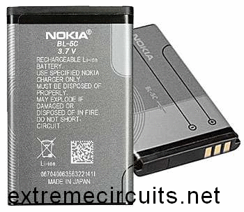
Normally mobile batteries have a lifespan of 2-5 years under normal usage. But then we have to replace them. Nowadays there are cheap replacement batteries which cost no more than 1$. But these low cost batteries run only 6-12 months. What to do with the used batteries, which can’t be reused in mobiles? Well, easy solution is to use the batteries in a circuit that requires less current. We can use them for LED lighting.

Do you have old unusable Mobile battery?
Hacks and Mods: Reuse Old Mobile Phone Battery for LED lighting
Normally mobile batteries have a lifespan of 2-5 years under normal usage. But then we have to replace them. Nowadays there are cheap replacement batteries which cost no more than 1$. But these low cost batteries run only 6-12 months. What to do with the used batteries, which can’t be reused in mobiles?
Hacks and Mods: Reuse Old Mobile Phone Battery for LED lighting
Well, easy solution is to use the batteries in a circuit that requires less current. We can use them for LED lighting. Thus your automatic lighting emergency light is ready which runs by your waste Mobile Battery. 


Source by : http://www.extremecircuits.net/2012/08/hacks-and-mods-reuse-old-mobile-phone.html
Read More..

Mobile Car Stereo Player

Using a mobile phone while driving is dangerous. It is also against the law. However, you can use your mobile phone as a powerful music player with the help of a stereo power amplifier. This does away with the need of a sophisticated in-dash car music system. Most mobile phones have a music player that offers a number of features including preset/manual sound equalisers. They have standard 3.5mm stereo sockets that allow music to be played through standard stereo headphones/sound amplifiers. Nokia 2700 classic is an example. 

Circuit diagram :
Circuit of mobile car stereo player
Mobile Car Stereo Player Circuit Diagram
 
A car audio amplifier with 3.5mm socket can be designed and simply connected to the mobile phone output via a shielded cable with suitable connectors/jacks (readymade 3.5mm male-to-male connector cable is a good alternative). Fig. 1 shows the circuit of car stereo player. It is built around popular single-chip audio power amplifier TDA1554Q (IC1). The TDA1554Q is an integrated class-B power amplifier in a 17-lead single-in-line (SIL) plastic power package. 

IC TDA1554Q contains four 11W identical amplifiers with differential input stages (two inverting and two non-inverting) and can be used for single-ended or bridge applications. The gain of each amplifier is fixed at 20 dB. Here it is configured as two 22W stereo bridge amplifiers. The amplifier is powered from the 12V car battery through RCA socket J2. Diode D1 protects against wrong-polarity connection. LED1 indicates the power status. 

Stereo Jack :
3.5mm stereo socket and (b) 3.5mm
(a) 3.5mm stereo socket and (b) 3.5mm Stereo Jack
 
Connect stereo sound signal from the 3.5mm headset socket of the mobile phone to audio input socket J1. When you play the music from your mobile, IC1 amplifies the input. The output of IC1 is fed to speakers LS1 and LS2 fitted at a suitable place in your car. Electrolytic capacitor C5 connected between pin 4 of IC1 and GND improves the supply-voltage ripple rejection. Components R2 and C4 connected at mute/standby pin (pin 14) of IC1 eliminate the switch on/off plop. The circuit is quite compact. A good-quality heat-sink assembly is crucial for IC1. Fig. 2 shows the stereo socket and stereo jack. 

Proposed enclosure Proposed enclosure

Assemble the circuit on a general-purpose PCB and enclose in a suitable cabinet. Small dimensions of the power amplifier make it suitable for being enclosed in a plastic (ABS) case with vent holes. Signal input socket, speaker output terminals, on/off switch, indicator, fuse holder and power supply socket are best located on the front panel of the enclosure as shown in Fig. 3. 

Author : T.K. Hareendran - Copyright : EFY
Read More..

Mobile phone Circuits to Get Even smaller

Transceivers, appliances such as mobile phones that can send and receive messages, have become smaller and smaller over the last few years, but users are about to experience a new meaning in miniaturisation. 

Research at The Hong Kong University of Science & Technology (HKUST) has successfully combined a unique system architecture and new circuit design techniques to reduce them in size like never before. 
Principal Investigator Dr Howard Luong said the handset of a typical mobile phone today may contain between 150 and 300 separate electrical components.
His research group proposed and demonstrated circuit techniques that make it possible to combine many of these components to a single chip and therefore to significantly reduce the size of circuitry (see example in graphic). A US patent has been granted for one of the circuit techniques. 
 
The transformation applies to the CMOS (Complimentary Metal-Oxide Semiconductor) manufacturing process, which can produce integrated circuits and systems with the highest integration level at the lowest cost. Applying new techniques to the CMOS process, Dr Luongs research enables many “off-chip components to be combined to realize a system-on-chip. But, he said, “this integration created great challenges in circuit implementation.” Part of the research was to solve the problems by new circuit design techniques.
 
The system architecture and circuitry go hand in hand, he added. “They must both work, or neither will be useful.
The resulting design gives the highest component integration in the smallest chip area ever reported, said Dr Luong.
In his design, all off-chip components are fitted into a central chip measuring 36 mm with packaging, and 8mm without being packaged.
Dr Luong’s miniaturisation method means appliances will soon be made for even lower cost and lower power consumption in addition to being much smaller in size and lighter in weight.
With the lowering of cost, size and power, many new and interesting applications will become possible and practical,” he said.
Low-power wireless transceivers, for example, could be integrated into implanted devices such as heart pacemakers to wirelessly transmit and receive information between patients and doctors or monitoring systems.
Wearable mobile phones as small as wrist watches at an affordable price could also become a reality.

Auther
Principal Investigator
Dr Howard Luong
Read More..

Monday, September 8, 2014

Mobile Cellphone Battery Charger

Charging of the mobile phone battery is a huge issue while traveling as power supply source is not usually available. In case you keep your mobile phone switched on continuously, its battery will go flat within to six hours, making the mobile phone useless. A fully charged battery becomes necessary when your distance from the nearest relay station increases. Here is a simple charger that replenishes the mobile phone battery within to hours. Fundamentally, the charger is a current-limited voltage source. Usually, mobile phone battery packs need three.6-6V DC & 180-200mA current for charging. These usually contain NiCd cells, each having one.2V rating. Current of 100mA is for charging the mobile phone battery at a slow rate. A 12V battery containing eight pen cells gives sufficient current (one.8A) to charge the battery connected across the output terminals.

Diagram  of cellphone charger

The schema also monitors the voltage level of the battery. It automatically cuts off the charging system when its output terminal voltage increases above the predetermined voltage level. Timer IC NE555 is used to charge & monitor the voltage level in the battery. Control voltage pin five of IC1 is supplied with a reference voltage of five.6V by zen-er diode ZD1. Threshold pin 6 is supplied with a voltage set by VR1 & trigger pin two is supplied with a voltage set by VR2. When the discharged mobile phone battery is connected to the schema, the voltage given to trigger pin two of IC1 is below 1/3Vcc & hence the flip-flop in the IC is switched on to take output pin three high.


When the battery is fully charged, the output terminal voltage increases the voltage at pin two of IC1 above the trigger point threshold. This switches off the flip-flop & the output goes low to terminate the charging method. Threshold pin 6 of IC1 is referenced at 2/3Vcc set by VR1. Transistor T1 is used to enhance the charging current. Value of R3 is critical in providing the necessary current for charging. With the given value of 39-ohm the charging current is around 180 mA.

The schema can be constructed on a tiny general-purpose PCB. For calibration of cut-off voltage level, use a variable DC power source. Connect the output terminals of the schema to the variable power supply set at 7V. Fine-tune VR1 in the middle position & slowly fine-tune VR2 until LED1 goes off, indicating low output. LED1 ought to turn on when the voltage of the variable power supply reduces below 5V. Enclose the schema in a tiny plastic case & use suitable connector for connecting to the cell phone battery.
Read More..