Showing posts with label speed. Show all posts

Wednesday, November 12, 2014

12V Speed Dimmer Controller Diagram Circuit

This handy circuit can be used as a speed controller for a 12V motor rated up to 5A (continuous) or as a dimmer for a 12V halogen or standard incandescent lamp rated up to 50W. It varies the power to the load (motor or lamp) using pulse width modulation (PWM) at a pulse frequency of around 220Hz.

SILICON CHIP has produced a number of DC speed controllers over the years, the most recent being our high-power 24V 40A design featured in the March & April 2008 issues. Another very popular design is our 12V/24V 20A design featured in the June 1997 issue and we have also featured a number of reversible 12V designs.Circuit looks like:

For many applications though, most of these designs are over-kill and a much simpler circuit will suffice. Which is why we are presenting this basic design which uses a 7555 timer IC, a Mosfet and not much else. Being a simple design, it does not monitor motor back-EMF to provide improved speed regulation and nor does it have any fancy overload protection apart from a fuse. However, it is a very efficient circuit and the kit cost is quite low.Parts layout:
Connection diagram:

There are many applications for this circuit which will all be based on 12V motors, fans or lamps. You can use it in cars, boats, and recreational vehicles, in model boats and model railways and so on. Want to control a 12V fan in a car, caravan or computer? This circuit will do it for you.Circuit diagram:

The circuit uses a 7555 timer (IC1) to generate variable width pulses at about 210Hz. This drives Mosfet Q3 (via transistors Q1 & Q2) to control the speed of a motor or to dim an incandescent lamp.Halogen lamps:While the circuit can dim 12V halogen lamps, we should point out that dimming halogen lamps is very wasteful. In situations where you need dimmable 12V lamps, you will be much better off substituting 12V LED lamps which are now readily available in standard bayonet, miniature Edison screw (MES) and MR16 halogen bases. Not only are these LED replacement lamps much more efficient than halogen lamps, they do not get anywhere near as hot and will also last a great deal longer.
Source: Silicon Chip 15 November 2008
Read More..

Thursday, September 18, 2014

Rotative Speed Regulator Borer Driller Controller

This rotative speed regulator circuit schematic allows to control the holing speed of your borer or driller machine. This project is based on the fact that if the load grows, the voltage decrease and current increase. Use this circuit to control the speed of revolutions of your drilling mill or bench drill.

Driller controller circuit schematic

Circuit Project: Rotative speed regulator borer, driller controller 


Source By : http://www.extremecircuits.net/2012/08/rotative-speed-regulator-borer-driller.html
Read More..

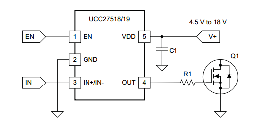
Simple 4A High Speed Low Side Gate Driver

The UCC27518 and UCC27519 single-channel, high-speed, low-side gate driver device is capable of effectively driving MOSFET and IGBT power switches. Using a design that inherently minimizes shoot-through current, UCC27518 and UCC27519 are capable of sourcing and sinking high, peak-current pulses into capacitive loads offering rail-to-rail drive capability and extremely small propagation delay typically 17 ns.

The UCC27518 and UCC27519 provide 4-A source, 4-A sink (symmetrical drive) peak-drive current capability at VDD = 12 V. The UCC27518 and UCC27519 are designed to operate over a wide VDD range of 4.5 V to 18 V and wide temperature range of -40°C to 140°C. Internal Under Voltage Lockout (UVLO) circuitry on VDD pin holds output low outside VDD operating range.

Circuit Project: 4A High-Speed Low-side Gate Driver
Features
  • Low-Cost, Gate-Driver Device Offering Superior Replacement of NPN and PNP Discrete Solutions
  • Pin-to-Pin Compatible With TI’s TPS2828 and the TPS2829
  • 4-A Peak Source and 4-A Peak Sink Symmetrical Drive
  • Fast Propagation Delays (17-ns typical)
  • Fast Rise and Fall Times (8-ns and 7-ns typical)
  • 4.5-V to 18-V Single Supply Range
  • Outputs Held Low During VDD UVLO (ensures glitch free operation at power-up and power-down)
  • CMOS Input Logic Threshold (function of supply voltage with hysteresis)
  • Hysteretic Logic Thresholds for High Noise Immunity
  • EN Pin for Enable Function (allowed to be no connect)
  • Output Held Low when Input Pins are Floating
  • Input Pin Absolute Maximum Voltage Levels Not Restricted by VDD Pin Bias Supply Voltage
  • Operating Temperature Range of -40°C to 140°C
  • 5-Pin DBV Package (SOT-23)
Device Uses
  • Switch-Mode Power Supplies
  • DC-to-DC Converters
  • Companion Gate Driver Devices for Digital Power Controllers
  • Solar Power, Motor Control, UPS
  • Gate Driver for Emerging Wide Band-Gap Power Devices (such as GaN)
Read More..

Friday, August 22, 2014

Junk box Fan Speed Controller

Junk-box Fan Speed Controller Circuit Diagram. My new home theatre receiver was getting rather hot in the close confines of its cabinet, with the temperature reaching over 40°C after only about 30 minutes of use. To help lower the temperature, I decided to install a fan in the cabinet. A 75mm hole was cut in the shelf under the receiver, and a 12V fan salvaged from an old computer power supply was mounted underneath. The fan was powered from a 12V DC plugpack. 

This did the job, keeping the temperature below 30°C even after prolonged use on a warm day. However, the fan was annoyingly loud when running at full speed. To reduce the noise level substantially, I built this fan speed controller with temperature feedback. The schema was culled from variety of ideas found on various sites on the internet, with the final schema designed from what was in the "junk box". Air temperature in the cabinet is sensed via an LM335 (TS1).
Junk-box Fan Speed Controller Circuit Diagram
 
junk-box-fan-speed-controller
Junk-box Fan Speed Controller Circuit Diagram

It is glued to a piece of aluminium about 25mm square with instant glue, which is then attached to the top of the receiver with "Blue-Tack". About 300mm of audio coax makes the connection back to the schema board. The LM335’s output rises 10mV per degree Centigrade. It is calibrated to zero output at -273°C, so at 20°C, the output will be 2.93V. This is applied to the non-inverting input of a 741 op amp (IC1). A 1N4733 5.1V Zener diode provides a voltage reference for the inverting input via trimpot VR1. The output of the op amp drives a TIP122 Darlington transistor (Q1), which in turn drives the fan motor. The op amp gain was calculated to give about 12V to the fan at 40°C. 
 
To keep the transistor cool, it is mounted on the metal base of a small plastic box, which is also used to house the components.  Initial setup should be performed with everything turned off and the ambient temperature at about 20°C. Adjust the 10-turn pot until the fan just stops running. I used a gasket made from foam strips and "blue-tacked" them between the feet of the receiver to direct all of the airflow through it. The temperature now remains at about 32°C, the fan runs very quietly and continues to run down for about 30 minutes after the receiver is switched off.


Author: Martin Cook - Copyright: Silicon Chip Electronics
Read More..