Showing posts with label 12v. Show all posts

Wednesday, November 12, 2014

12V Speed Dimmer Controller Diagram Circuit

This handy circuit can be used as a speed controller for a 12V motor rated up to 5A (continuous) or as a dimmer for a 12V halogen or standard incandescent lamp rated up to 50W. It varies the power to the load (motor or lamp) using pulse width modulation (PWM) at a pulse frequency of around 220Hz.

SILICON CHIP has produced a number of DC speed controllers over the years, the most recent being our high-power 24V 40A design featured in the March & April 2008 issues. Another very popular design is our 12V/24V 20A design featured in the June 1997 issue and we have also featured a number of reversible 12V designs.Circuit looks like:

For many applications though, most of these designs are over-kill and a much simpler circuit will suffice. Which is why we are presenting this basic design which uses a 7555 timer IC, a Mosfet and not much else. Being a simple design, it does not monitor motor back-EMF to provide improved speed regulation and nor does it have any fancy overload protection apart from a fuse. However, it is a very efficient circuit and the kit cost is quite low.Parts layout:
Connection diagram:

There are many applications for this circuit which will all be based on 12V motors, fans or lamps. You can use it in cars, boats, and recreational vehicles, in model boats and model railways and so on. Want to control a 12V fan in a car, caravan or computer? This circuit will do it for you.Circuit diagram:

The circuit uses a 7555 timer (IC1) to generate variable width pulses at about 210Hz. This drives Mosfet Q3 (via transistors Q1 & Q2) to control the speed of a motor or to dim an incandescent lamp.Halogen lamps:While the circuit can dim 12V halogen lamps, we should point out that dimming halogen lamps is very wasteful. In situations where you need dimmable 12V lamps, you will be much better off substituting 12V LED lamps which are now readily available in standard bayonet, miniature Edison screw (MES) and MR16 halogen bases. Not only are these LED replacement lamps much more efficient than halogen lamps, they do not get anywhere near as hot and will also last a great deal longer.
Source: Silicon Chip 15 November 2008
Read More..

Monday, November 3, 2014

12V Flourescent Lamp Inverter

Fluorescent tubes use far less energy than incandescent lamps and fluorescent tubes last a great deal longer as well. Other advantages are diffuse, glare-free lighting and low heat output. For these reasons, fluorescent lighting is the natural choice in commercial and retail buildings, workshops and factories. For battery-powered lighting, fluorescent lights are also the first choice because of their high efficiency. The main drawback with running fluorescent lights from battery power is that an inverter is required to drive the tubes.

12V Fluorescent Lamp Inverter Circuit diagram:

12-volt

Fig.1: two switch-mode circuits are involved here: the DC-DC inverter involving IC1, Q1 & Q2 and the fluoro tube driver which converts high voltage DC to AC via IC3 and Q3 & Q4 in a totem-pole circuit.
Inverter efficiency then becomes the major issue. There are many commercial 12V-operated fluorescent lamps available which use 15W and 20W tubes. However, it is rare to see one which drives them to full brilliance. For example, a typical commercial dual 20W fluorescent lamp operating from 12V draws 980mA or 11.8W. Ignoring losses in the fluorescent tube driver itself, it means that each tube is only supplied with 5.9W of power which is considerably less than their 20W rating. So while the lamps do use 20W tubes, the light output is well below par.

Warning:
This circuit generates in excess of 300V DC which could be lethal. Construction should only be attempted by those experimenced with mains-level voltages and safety procedures.
Read More..

Cheap 12V to 220V Inverter

Even though today’s electrical appliances are increasingly often self-powered, especially the portable ones you carry around when camping or holidaying in summer, you do still sometimes need a source of 230 V AC - and while we’re about it, why not at a frequency close to that of the mains? As long as the power required from such a source remains relatively low - here we’ve chosen 30 VA - it’s very easy to build an inverter with simple, cheap components that many electronics hobbyists may even already have.

Though it is possible to build a more powerful circuit, the complexity caused by the very heavy currents to be handled on the low-voltage side leads to circuits that would be out of place in this summer issue. Let’s not forget, for example, that just to get a meager 1 amp at 230 VAC, the battery primary side would have to handle more than 20 ADC!. The circuit diagram of our project is easy to follow. A classic 555 timer chip, identified as IC1, is configured as an astable multivibrator at a frequency close to 100 Hz, which can be adjusted accurately by means of potentiometer P1.

Cheap 12V to 220V Inverter Circuit diagram:

Inverter

As the mark/space ratio (duty factor) of the 555 output is a long way from being 1:1 (50%), it is used to drive a D-type flip-flop produced using a CMOS type 4013 IC. This produces perfect complementary square-wave signals (i.e. in antiphase) on its Q and Q outputs suitable for driving the output power transistors. As the output current available from the CMOS 4013 is very small, Darlington power transistors are used to arrive at the necessary output current. We have chosen MJ3001s from the now defunct Motorola (only as a semi-conductor manufacturer, of course!) which are cheap and readily available, but any equivalent power Darlington could be used.

These drive a 230 V to 2 × 9 V center-tapped transformer used ‘backwards’ to produce the 230 V output. The presence of the 230 VAC voltage is indicated by a neon light, while a VDR (voltage dependent resistor) type S10K250 or S07K250 clips off the spikes and surges that may appear at the transistor switching points. The output signal this circuit produces is approximately a square wave; only approximately, since it is somewhat distorted by passing through the transformer. Fortunately, it is suitable for the majority of electrical devices it is capable of supplying, whether they be light bulbs, small motors, or power supplies for electronic devices.

PCB layout:
invertor-circuit-diagram


Parts List :
Resistors
R1 = 18k?
R2 = 3k3
R3 = 1k
R4,R5 = 1k?5
R6 = VDR S10K250 (or S07K250)
P1 = 100 k potentiometer
Capacitors
C1 = 330nF
C2 = 1000 µF 25V
Semiconductor
T1,T2 = MJ3001
IC1 = 555
IC2 = 4013
Miscellaneous
LA1 = neon light 230 V
F1 = fuse, 5A
TR1 = mains transformer, 2x9V 40VA (see text)
4 solder pins

Note that, even though the circuit is intended and designed for powering by a car battery, i.e. from 12 V, the transformer is specified with a 9 V primary. But at full power you need to allow for a voltage drop of around 3 V between the collector and emitter of the power transistors. This relatively high saturation voltage is in fact a ‘shortcoming’ common to all devices in Darlington configuration, which actually consists of two transistors in one case. We’re suggesting a PCB design to make it easy to construct this project; as the component overlay shows, the PCB only carries the low-power, low-voltage components.

The Darlington transistors should be fitted onto a finned anodized aluminum heat-sink using the standard insulating accessories of mica washers and shouldered washers, as their collectors are connected to the metal cans and would otherwise be short-circuited. An output power of 30 VA implies a current consumption of the order of 3 A from the 12 V battery at the ‘primary side’. So the wires connecting the collectors of the MJ3001s [1] T1 and T2 to the transformer primary, the emitters of T1 and T2 to the battery negative terminal, and the battery positive terminal to the transformer primary will need to have a minimum cross-sectional area of 2 mm2 so as to minimize voltage drop.

The transformer can be any 230 V to 2 × 9 V type, with an E/I iron core or toroidal, rated at around 40 VA. Properly constructed on the board shown here, the circuit should work at once, the only adjustment being to set the output to a frequency of 50 Hz with P1. You should keep in minds that the frequency stability of the 555 is fairly poor by today’s standards, so you shouldn’t rely on it to drive your radio-alarm correctly – but is such a device very useful or indeed desirable to have on holiday anyway? Watch out too for the fact that the output voltage of this inverter is just as dangerous as the mains from your domestic power sockets.

So you need to apply just the same safety rules! Also, the project should be enclosed in a sturdy ABS or diecast so no parts can be touched while in operation. The circuit should not be too difficult to adapt to other mains voltages or frequencies, for example 110 V, 115 V or 127 V, 60 Hz. The AC voltage requires a transformer with a different primary voltage (which here becomes the secondary), and the frequency, some adjusting of P1 and possibly minor changes to the values of timing components R1 and C1 on the 555.


Read More..

Thursday, October 23, 2014

12V 3A Power Supply Circuit Diagram

This circuit provides a 12V regu-lated power supply with output current up to 3 amperes. It is spe-cially designed for use with 2m handheld rigs with linear power amplifier and CB portable QRP rigs. The circuit uses monolithic IC CA3085 voltage regulator in 8-lead TO-5 package.  Its salient features include good load and line regulation, output current up to 100 mA (which can be increased to several amperes with additional pass transistors), output short-circuit protection, and lower input voltage.  A low power dissipation is achieved by driving external series-pass transistor 2N4241 (T1) from  pin 2 of CA3085.
Circuit diagram :
12V, 3A Power Supply-Circuit-Diagram
12V, 3A Power Supply Circuit Diagram
Normal output pin 8 is returned to ground via diodes D3 and D4 to ensure error am-plification operation in the linear region. Ripple rejection is approximately 50 dB on no load and 35 dB on full load.  A 2x2x2.5cm aluminium heat sink fas-tened onto a 1.5mm blackened aluminium sheet of 12.5cm2 area on 2N4241 helps the circuit in dissipating heat without ex-ceeding maximum device ratings. CA3085 can dissipate up to 650mW power in free air, without any heat sink.  AFCO-make C-05-4 heat sink is suitable for this IC. An improper heat sink may cause device junction temperature to ex-ceed the limit, resulting in progressive deterioration of the device. 


Read More..

12V Step Down Dc Converter Using ADP2300 ADP2301

Using ADP2300 ADP2301 step-down dc dc regulators with integrated power MOSFET, can be designed a very simple DC DC voltage converter. Output voltage delivered by these circuits can be adjusted from 0.8 volts, up to 0.85xVin , with ±2% accuracy. The maximum output current that can be provided by ADP2300 ADP2301 regulators is up to 1.2 A load current.

12V Step-Down Dc Converter Circuit Diagram
12V Step-Down Dc-Converter-Circuit Diagram
12V Step-Down Dc-Converter-ADP2301
There are two frequency options: the ADP2300 runs at 700 kHz, and the ADP2301 runs at 1.4 MHz. These options allow users to make decisions based on the trade-off between efficiency and total solution size. Current-mode control provides fast and stable line and load transient performance.  Bellow you an see two design examples, which require few common electronic components.First circuit will provide a 2.5V output at a maximum current of 1.2A from an input voltage of 12 volts. Second circuit will provide a 5V output at a maximum current of 1.2A from an input voltage of 12 volts.
Read More..

Wednesday, October 22, 2014

12V Touch Switch Exciter

This circuit is designed to generate a 20KHz pseudo sine wave signal that can power about 50 remote touch activated switch circuits.  It can support a cable length of about 2500 feet.  A typical remote switch circuit is also shown as well as a receiver circuit for those switches.


Source: DiscoverCircuits
Read More..

12V Powered 12V Lead Acid Battery Charger with Indicator

Some of you might wonder why a charger is needed at all, to charge a 12 Volt battery from a 12 Volt source! Well, firstly the "12 Volt" source will typically vary anywhere from 11 Volt to 15 Volt, and then a battery needs a controlled charge current and voltage, which cannot result from connecting it directly to a voltage source. The charger described here is intended for charging small 12 Volt lead acid batteries, such as the gelled or AGM batteries of capacities between about 2 and 10 Ah, using a cars electrical system as power source, regardless of whether the car engine is running or not. I built this charger many years ago, I think I was still in school back then. On request of a reader of my web site, Im publishing it now, despite being a rather crude circuit.

12V Powered 12V Lead Acid Battery Charger with Indicator
It works, it is uncritical to build, and uses only easy-to-find parts, so it has something in its favor. The downside is mainly the low efficiency: This charger wastes about as much power as it puts into the battery. The charger consists of two stages: The first is a capacitive voltage doubler, which uses a 555 timer IC driving a pair of transistors connected as emitter followers, which in turn drive the voltage doubler proper. The doubler has power resistors built in, which limit the charging current. The second stage is a voltage regulator, using a 7815 regulator IC. Its output is applied to the battery via a diode, which prevents reverse current and also lowers the voltage a bit.

12V Powered 12V Lead Acid Battery Charger with Indicator
The resulting charge voltage is about 14.4V, which is fine for charging a gelled or AGM battery to full charge, but is too high as a trickle charger, so dont leave this charger permanently connected to a battery. If you would like to do just that, then add a second diode in series with D3! There is a LED connected as a charge indicator. It will light when the charge current is higher than about 150mA. The maximum charge current will be roughly 400mA. There is an auxiliary output, that provides about 20V at no load (depending on input voltage), and comes down as the load increases. I included this for charging 12V, 4Ah NiCd packs, which require just a limited current but not a limited voltage for charging.

12V Powered 12V Lead Acid Battery Charger with Indicator
Note that if the charge output is short-circuited, the overcurrent protection of U2 will kick in, but the current is still high enough to damage the diodes, if it lasts. So, dont short the output! If instead you short the auxiliary output, the fuse should blow. I built this charger into a little homemade aluminum sheet enclosure, using dead-bug construction style. Not very tidy, but it works. Note the long leads on the power resistors. They are necessary, because with shorter leads the resistors will unsolder themselves, as they get pretty hot! The transistors and the regulator IC are bolted to the case, which serves as heat sink. The transistors dont heat up very much, but the IC does.

 
Source: Homo Ludens
Read More..

Monday, October 20, 2014

Build a 12V To 24V DC DC Converter Circuit Diagram

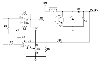
Build a 12V To 24V DC-DC Converter Circuit Diagram.This simple 12V To 24V DC-DC Converter Circuit Diagram can provide up to 24V from a 12V source. It can be used to run radios, small lights, relays, horns and other 24V accessories from a 12V vehicle with a maximum draw of about 800mA. 

It can be used to charge one 12V battery from another, or step up the voltage just enough to provide necessary overhead for a 12V linear regulator. Using one op-amp as a square wave oscillator to ring an inductor and another op-amp in a feedback loop, it wont drift around under varying loads, providing a stable 24V source for many applications. With a wide adjustment in output this circuit has many uses.

 12V To 24V DC-DC Converter Circuit Diagram

12V To 24V DC-DC Converter Circuit Diagram

Parts

Part
Total Qty.
Description
Substitutions
R1, R2, R3, R4, R8, R76100K 1/4W Resistor
R51470 Ohm 1/2W Resistor
R6110K Linear Pot
C110.01uF Mylar Capacitor
C210.1uF Ceramic Disc Capacitor
C31470uF 63V Electrolytic Capacitor
D111N4004 Rectifier Diode
D21BY229-400 Fast Recovery DiodeSee Notes
Q11BC337 NPN Power Transistor
U11LM358 Dual Op Amp IC
L11See Notes
MISC1Board, Wire, Socket For U1, Case, Knob For R6, Heatsink for Q1

Notes

  • R6 sets the output voltage. This can be calculated by Vout = 12 x (R8/(R8+R7)) x (R6B/R6A).
  • L1 is made by winding 60 turns of 0.63MM magnet wire on a toroidial core measuring 15MM (OD) by 8MM (ID) by 6MM (H).
  • D2 can be any fast recovery diode rated at greater then 100V at 5A. It is very important that the diode be fast recovery and not a standard rectifier.
  • Q1 will need a heatsink.


Sourced By Circuitsstream
Read More..

Friday, October 17, 2014

Build a100W Inverter 12V to 220V Circuit Diagram

How to Build a100W Inverter 12V to 220V Circuit Diagram. When use the electric appliances that want 220V AC 50HZ, which have small-sized about 100Watt not exceed. By when you apply outside home, as a result have to have Mini power inverter about 100Watt, perform modify from work electricity forces of battery 12V give tall fair the work. 

100W Inverter 12V to 220V Circuit Diagram
 
100W
 If you are New user electronics or want to economize or want to build electronics project use by oneself. I begs for to advise this circuit , because it uses , transistor number BC557 or the number replaces, perform oscillator generator. Then have power transistor 2N3055 numbers perform to drive coil transformer for converter voltage give tall go up 220V AC 50HZ at the electric power about 100 watt not exceed. When apply to transformer about 2A-3A. Picture circuit detail and like model PCB Board.

 PCB


Read More..

Sunday, October 5, 2014

2N3055 DC 12V to DC 6V 7 5V 9V Converter


This circuit is DC to DC converter model step down voltage. That can modify voltage input 12V DC from be DC 6V , 7.5V and 9V by have the size current about 1A – 2 Amp think. Be easy circuit use Zener diode maintain one’s position voltage. Be stable and have transistor 2N3055. 
Read More..

Wednesday, September 24, 2014

6V 12V Constant Current Battery Charger Circuit PCB Layout Added

The circuit diagram of the charger shown in Fig.1 is centered around the L200 type voltage regulator IC, which ensures constant charging voltage to any connected 6V, 12V battery.
R2 and R3 are the current limiting resistors. The charging current is selected by altering the values of R2 and R3. Strictly, the necessity of R2 holds good if the charging current exceeds 500 mA. The current required for charging is obtained by the relation: l(charging) = 0.45(R2+R3)/ R2R3

The circuit diagram and PCB layout of the above explained 6V 12V constant current battery charger is shown below:


Read More..

Monday, September 22, 2014

500W low cost 12V to 220V inverter circuit and explanation

Using this circuit you can convert the 12V dc in to the 220V Ac. In this circuit 4047 is use to generate the square wave of 50hz and amplify the current and then amplify the voltage by using the step transformer.


author: Ashad Mustufa
e-mail: mustufa66@hotmail.com
web site: http://www.electronics-lab.com

Circuit diagram

How to calculate transformer rating
The basic formula is P=VI and between input output of the transformer we have Power input = Power output
For example if we want a 220W output at 220V then we need 1A at the output. Then at the input we must have at least 18.3V at 12V because: 12V*18.3 = 220v*1
So you have to wind the step up transformer 12v to 220v but input winding must be capable to bear 20A.


Read More..

Saturday, September 20, 2014

TL594 12V DC Switch Mode Power Supply Wiring diagram Schematic

In recent years, the use of switch mode power supply (SMPS) has become more comon as more applications demand for greater power eficiency. It makes use of semiconductor (mostly MOSFET) fast switches to switch DC input that has been rectified at high frequency. The advantages of high frequency switching are that it reduces the size of inductor, capacitors & transformer used. Other advantages of switching power supply over linear power supply are :

1) High Efficiency (up to 90% and above for nice design).
2) Output can be higher than input.
3) Able to operate over a variety of input power supply.
4) Able to have over output.

The setback of using SMPS compared to linear power supply is that it generates electrical noise which contributes to electromagnetic compatibility design issues & more part count.

Buck Converter SMPS
The SMPS schema below from Power Integration makes use of LNK304 as its high frequency switch. Take note that this schema is non isolated type which means that the output is not electrically isolated from the input & all testing ought to be completed using an isolation transformer to provide the AC line input to the board.

Make positive that you have electrical safety knowledge & experience before you embark on doing this project.

12V DC Switch Mode Power Supply Circuit Diagram

12V


Read More..

Thursday, September 18, 2014

12v Light Dark Switch

Often, for certain low voltage lighting systems; you would like to turn off the lights during the bright light of the day.  Most commercial day/night switches are designed for AC lighting.  This hobby circuit below was designed for a 12v DC system.  But, it could be modified for other voltage as well.  It uses an inexpensive photo-transistor as the light detector.  An n-channel FET is used to switch power to the lights.  A transistor circuit is included to provide some hysteresis.  

This keeps the circuit from fluttering the light during the transition from day to night and night to day.  It is recommended that a plastic tube be placed over the transistor to prevent it from being illuminated by the lights it is controlling.  By selecting the appropriate power FET, the circuit could control over 100 watts worth of 12v lighting.   (July 22, 2008)


Circuit Project:12v LightDark Switch
 
 
Source: DiscoverCircuits
Read More..

Wednesday, September 10, 2014

4 5V To 12V DC


This ic 4.5V to 12V boost schema.You all can get lots of advantages through this schema.Here I have used famous IC LM2698.


Note

# input supply voltage range is 2.2V to 17V DC and outputs ranging from 2.2V to 17V DC

# IC can deliver only up to 400mA.So dont connect lodes more than that

# Build this schema on a PCB
Read More..