Showing posts with label with. Show all posts
Showing posts with label with. Show all posts
Wednesday, November 19, 2014
Line Follower Robot with AVR ATMega8535
Line Follower Robot with AVR ATMega8535 - Make the robot line follower is exciting, especially for those who like to friends experimented with AVR microcontroller ATMega. "Line Follower Robot" is a robot designed to follow the trail (can be a line putus2 line or even a point to point). Creating a Line Follower Robot uses an AVR microcontroller ATMega 8535 is very possible and very reliable. Due to the design of a Line Follower Robot should we think that the trail will be followed step by step Line Follower Robot will be made to track or path in Line Follower Robot is passed. And of the Line Follower Robot needs tersbut feature2 owned by AVR microcontroller ATMega 8535 is sufficient and meets the needs of the Line Follower Robot. Line Follower Robot in the article with AVR ATMega8535 I made a simple graffiti to be possessed by a Line Follower Robot.
Line Follower Robot Block Diagram of the AVR ATMega8535
| Block Diagram of Line Follower Robot with AVR ATMega 8535 |
Function Block Diagram of Line Follower Robot with AVR ATMega 8535 :
- Line Follower Robot Sensor on can use a photo diode or photo transistor, this section serves to detect the presence of trajectory track.
- Keypad, this part of the function buttons to start / stop Line Follower Robot and as voters Line Follower Robot configuration settings for the field will be going through.
- Display, a part which serves to show the option of setting and the setting (it is enough that needs to be in view) of this section or the viewer can use a 7 segment LCD.
- Motor Driver, this part of a series of H Bridge DC motor driver. This section controls the motor in langsun. This section is an AVR microcontroller interface anatara ATMega with DC motor. I like to use the IC motor driver L298 family.
- ATMega8535 AVR microcontrollers, this section is the part that determines where the robot will be taken based on the data from the sensor. This section is set langkah2 Line Follower Robot in the conquest of the track.

Tuesday, November 18, 2014
Power supply with Z2C
Power supply with Z2C tubes are designed specifically to provide power supply voltage to the EL-34 tube amplifier push-pull in the previous article. Power supply with Z2C tube to tube power amplifier is made with a tube rectifier Z2C. Just as the power supply for power amplifier tube earlier, power supply also uses a filter 3 levels with kapsitor electrolyte. Circuit power supply with tube rectifier Z2C can give +210 VDC output voltage. A complete range of power supply for power amplifier tube can be seen in thethe following figure .
Z2C on the rectifier tube in power supply with tube above require a supply voltage for the filaments taken from the other side of the transformer secondary. Power supply with Z2C tube is a power supply that dapt used as a substitute power supply for power amplifier tubes with a diode in previous articles.
Monday, November 17, 2014
10W audio power amplifier with bass boost
 As the amplifier circuit also uses a number of frequencies to drive the loudspeaker, the bass frequencies will be reduced. Therefore need to be plugged the bass-boost control at fedback loop amplifier, this is done to overcome the decline in quality.
Graph bass can reach a maximum at +16.4 dB @ 50Hz.
This circuit can be connected directly to the CD player, tuner, and tape recorders. Q3 and Q4 must be in pairs with a heatsink.
Adjust the volume control at minimum position and R3 with a minimum value of resistance as well. try enabling circuit R3 da set up to read the flow of about 20 to 25mA. Wait for 15 minutes, connect the ground at J1, P1, C2, C4 C3dan. Connect also C9 at the output ground.

For his series of power supply you can use the following scheme that fits perfectly with this amplifier.

Power supply with driver TEA1507
Power supply with driver TEA1507 is mostly used by TV branded PHILIPS. Power Supply has an efficiency rate of up to 90% - thus requiring less cooling, as well as stand-by power required is less than 1 watt.
Power Supply with TEA driver is equipped with a variety of surge protector that has a high reliability - not easily damaged if any part of a damaged power supply circuit and power transistor or FET heat is not easily damaged. Power supply circuits are dapatapat working on ac input voltage between 85 up to 275v. The way it works with the driver circuit power supply TEA 1507 is quite simple, so easy tracking of damage to the circuit.
The picture above is the basic power supply circuit with TEA1507
Tuesday, November 4, 2014
Simple Detector with Amplification
A simple shortwave radio detector is neither very sensitive nor very selective. However, with a little extra amplification we can improve the reception performance significantly.
The additional circuit is designed to compensate for the losses in the resonant circuit. A transistor is used to amplify the RF signal and feed it back into the resonant circuit. When the gain is set correctly we can make the amount of this feedback exactly equal to the losses. The resonant circuit is then critically damped and has a very high Qfactor. Now we can separate transmissions that are just 10 kHz apart, and we can tune in to very weak stations.
Detector with Amplification Circuit Diagram :
The tuning capacitor used has two gangs of vanes with capacitances of 240 pF and 80 pF. These two gangs are connected in parallel to make a 320 pF variable capacitance. The air-cored inductor has 25 turns on a diameter of 10 mm, with taps at 5-turn intervals. The resonant circuit so formed is capable of covering the full shortwave band from 5 MHz to 25 MHz.
The short wave detector can be connected to a power amplifier, or, for exam-ple, amplified PC loudspeakers. The antenna does not have to be very long: in experiments we used a one metre length of wire. Tuning the radio involves adjusting the variable capacitor to bring in the station and then adjusting the gain of the feed-back circuit for optimal output volume. If the potentiometer is turned up too far, the receiver will go into self-oscillation and become a mini-transmitter. At the optimal setting the sound quality is very pleasant and certainly no worse than many ordinary shortwave radios.
If you find shortwave detectors that use a battery and an amplifier a little new-fangled, you can get your fix of nostalgia by dispensing with the battery and connecting a crystal earpiece to the detector’s output. The radio will of course also work without the feedback circuit, but with rather poorer performance.
Wednesday, October 29, 2014
LG Gx2 5 7 inch cell with the same laser technology in LG Camera G3
LG is presenting streak new cell before IFA 2014 Earlier this week the company introduced the LG Stylus G3 to challenge the Samsung Galaxy Note, but apparently thats not all you have prepared and presented the LG Gx2, which can be easily confused with the LG G2x years ago.
The new LG cell Gx2 also wants to enter the territory of the Samsung Galaxy Note to have a 5.7 inch screen, but its specifications are still being average and not high end.
Gx2 LG screen has a resolution HD (720p), a quad-core 1.2GHz processor, 1.5GB of RAM and 8GB of storage.
Additionally, the cell has a ATTERY of 3,200mAh, a rear 8 megapixel camera, 1.3 megapixel front camera and battery 3,200mAh. The rear camera has the same technology found in the LG G3, mainly the laser autofocus.
LG has not announced when it would be released in that country and what would be its price. However, there is the possibility that, for the moment, leave only in Asia, but do not rule out the possibility of reaching other markets in the future.
The new LG cell Gx2 also wants to enter the territory of the Samsung Galaxy Note to have a 5.7 inch screen, but its specifications are still being average and not high end.
Gx2 LG screen has a resolution HD (720p), a quad-core 1.2GHz processor, 1.5GB of RAM and 8GB of storage.
Additionally, the cell has a ATTERY of 3,200mAh, a rear 8 megapixel camera, 1.3 megapixel front camera and battery 3,200mAh. The rear camera has the same technology found in the LG G3, mainly the laser autofocus.
LG has not announced when it would be released in that country and what would be its price. However, there is the possibility that, for the moment, leave only in Asia, but do not rule out the possibility of reaching other markets in the future.
Monday, October 27, 2014
How Regulator with 2 Photocoupler
Working of Regulator with 2 Photocoupler that is :
- Photocoupler N901 - used as a coupling-off control on the regulator by mikrokontrol. Which is set high and low voltage B + (st-by at the B + voltage is low). Control of the pin-37 POWER mikrokontrol → V610 → VD913 V908 → N901.
- Photocoupler N903 - used to control on-off the regulator of X-ray circuit protector. X-ray protector circuit of flyback → VD451 → VD452 → SCR VS472. If the flyback voltage regulator over the job will automatically be turned off by N903
- To disable the X-ray circuit protector, it can be temporarily removed photocoupler N903 first. In normal conditions the voltage at the transistor V474 should be zero.

 |
| Regulator Schematics |
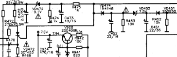
- Disable by removing the first circuit protectors N903
- Check the voltage of 300V
- Check all transistors
- Check the start voltage of 300V by R909 >> R906 to the base of transistor power regulator
- Check the feedback C910 >> R904 (to oscillate)
Wednesday, October 22, 2014
12V Powered 12V Lead Acid Battery Charger with Indicator
Some of you might wonder why a charger is needed at all, to charge a 12 Volt battery from a 12 Volt source! Well, firstly the "12 Volt" source will typically vary anywhere from 11 Volt to 15 Volt, and then a battery needs a controlled charge current and voltage, which cannot result from connecting it directly to a voltage source. The charger described here is intended for charging small 12 Volt lead acid batteries, such as the gelled or AGM batteries of capacities between about 2 and 10 Ah, using a cars electrical system as power source, regardless of whether the car engine is running or not. I built this charger many years ago, I think I was still in school back then. On request of a reader of my web site, Im publishing it now, despite being a rather crude circuit.

It works, it is uncritical to build, and uses only easy-to-find parts, so it has something in its favor. The downside is mainly the low efficiency: This charger wastes about as much power as it puts into the battery. The charger consists of two stages: The first is a capacitive voltage doubler, which uses a 555 timer IC driving a pair of transistors connected as emitter followers, which in turn drive the voltage doubler proper. The doubler has power resistors built in, which limit the charging current. The second stage is a voltage regulator, using a 7815 regulator IC. Its output is applied to the battery via a diode, which prevents reverse current and also lowers the voltage a bit.

The resulting charge voltage is about 14.4V, which is fine for charging a gelled or AGM battery to full charge, but is too high as a trickle charger, so dont leave this charger permanently connected to a battery. If you would like to do just that, then add a second diode in series with D3! There is a LED connected as a charge indicator. It will light when the charge current is higher than about 150mA. The maximum charge current will be roughly 400mA. There is an auxiliary output, that provides about 20V at no load (depending on input voltage), and comes down as the load increases. I included this for charging 12V, 4Ah NiCd packs, which require just a limited current but not a limited voltage for charging.

Note that if the charge output is short-circuited, the overcurrent protection of U2 will kick in, but the current is still high enough to damage the diodes, if it lasts. So, dont short the output! If instead you short the auxiliary output, the fuse should blow. I built this charger into a little homemade aluminum sheet enclosure, using dead-bug construction style. Not very tidy, but it works. Note the long leads on the power resistors. They are necessary, because with shorter leads the resistors will unsolder themselves, as they get pretty hot! The transistors and the regulator IC are bolted to the case, which serves as heat sink. The transistors dont heat up very much, but the IC does.

It works, it is uncritical to build, and uses only easy-to-find parts, so it has something in its favor. The downside is mainly the low efficiency: This charger wastes about as much power as it puts into the battery. The charger consists of two stages: The first is a capacitive voltage doubler, which uses a 555 timer IC driving a pair of transistors connected as emitter followers, which in turn drive the voltage doubler proper. The doubler has power resistors built in, which limit the charging current. The second stage is a voltage regulator, using a 7815 regulator IC. Its output is applied to the battery via a diode, which prevents reverse current and also lowers the voltage a bit.

The resulting charge voltage is about 14.4V, which is fine for charging a gelled or AGM battery to full charge, but is too high as a trickle charger, so dont leave this charger permanently connected to a battery. If you would like to do just that, then add a second diode in series with D3! There is a LED connected as a charge indicator. It will light when the charge current is higher than about 150mA. The maximum charge current will be roughly 400mA. There is an auxiliary output, that provides about 20V at no load (depending on input voltage), and comes down as the load increases. I included this for charging 12V, 4Ah NiCd packs, which require just a limited current but not a limited voltage for charging.

Note that if the charge output is short-circuited, the overcurrent protection of U2 will kick in, but the current is still high enough to damage the diodes, if it lasts. So, dont short the output! If instead you short the auxiliary output, the fuse should blow. I built this charger into a little homemade aluminum sheet enclosure, using dead-bug construction style. Not very tidy, but it works. Note the long leads on the power resistors. They are necessary, because with shorter leads the resistors will unsolder themselves, as they get pretty hot! The transistors and the regulator IC are bolted to the case, which serves as heat sink. The transistors dont heat up very much, but the IC does.
Source: Homo Ludens
Thursday, October 16, 2014
Simple HiFi Expandor Circuit Diagram with De emphasis
This is the schematic design of HiFi Expandor Circuit with De-emphasis. The circuit is based NE570. The NE570 can be used to construct a high performance compandor suitable for use with music. This type of system can be used for noise reduction in tape recorders, transmission systems, bucket brigade delay lines, and digital audio systems. The circuits to be described contain features which improve performance, but are not required for all applications.
HiFi Expandor Circuit Diagram

The expandor to complement the compressor is shown in the above circuit. Here an external op amp is used for high slew rate. Both the compressor and expandor have unity gain levels of 0dB. Trim networks are shown for distortion (THD) and DC shift. The distortion trim should be done first, with an input of 0dB at 10kHz. The DC shift should be adjusted for minimum envelope bounce with tone bursts. When applied to consumer tape recorders, the subjective performance of this system is excellent.
Saturday, October 11, 2014
Flasher with LED high Intensity Circuit Diagram
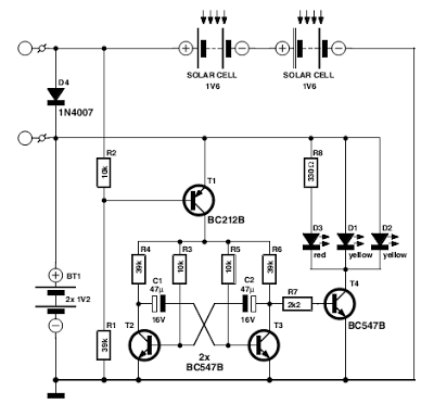
This Flasher with LED high Intensity Circuit Diagram was designed as a flasher warning and was originally mounted on a bicycle. White LEDs are only recommended if the circuit is used as a bicycle front light and red LEDs only when used as a taillight. During the day, the two solar cells carry two 1.6 V AA batteries. In the darkness, the cell voltage disappears solar energy and batteries are automatically diverted to the circuit. The frequency of blinking (flashing) is about one per second.
Flasher with LED high Intensity Circuit Diagram
If you liked this article,Take a few Seconds to Share this and leave comments
Thursday, September 18, 2014
Laptops Cord Stays off Your Lap with this Clip
Someone just got this trick works on all the uni body Mac Books and helps keep your wires and cord under control.

This clip is especially bendy if you are lounging on the sofa with the power-cord-side in towards the cushions. It keeps your MacBooks power cord under control with this trick and to stop it from tugging in you. Its built-in cable clip the one that keeps your cord wrapped around the power brick and clip it to the side of your laptops screen.
This clip is especially bendy if you are lounging on the sofa with the power-cord-side in towards the cushions. It keeps your MacBooks power cord under control with this trick and to stop it from tugging in you. Its built-in cable clip the one that keeps your cord wrapped around the power brick and clip it to the side of your laptops screen.

The cable pulls it up off your lap and keeps it neat and tidy not to mention free of crazy fall across the keyboard loops.
Sunday, September 14, 2014
Classical audio power amplifier with IT and OT transformer
The circuit is devote to the radio receiver in which sound ( the gear ) is weak. With the help of this tool , which initially sounds as if far to be clearly audible. Power amplifier does not require much electrical current source , because all components are not up to over 1 Mega . But the result was incredible because it can enhance the power of catching the wave signal.

Troubleshooting :
Wether transistors placement is correct ?
Placement Elco ?
Check are cable .
If all components have benn checked , and the damaged has been replaced . Then try , turn the potentiometer slowly and listen to how the sound output by the speaker.
Read More..
Troubleshooting :
Wether transistors placement is correct ?
Placement Elco ?
Check are cable .
If all components have benn checked , and the damaged has been replaced . Then try , turn the potentiometer slowly and listen to how the sound output by the speaker.
Saturday, September 13, 2014
Compressor Circuit with 570 571 Compandor IC
Compressor Circuit with 570/571 Compandor IC schema provide high gain for low amplitude input and provide low gain for high amplitude input. This action, in effect, produce a nearly constant amplitude even though the input has very high dynamic range (very high amplitude variation from time to time). The action of compression like this is needed in some situation, such as in maximizing modulation depth in broadcasting, or sustaining electric guitar signal which has very high variation between the plucking time and fading out. The following schema has complementary input/output characteristic and unity gain at 0.775 VRMS input. Voltage gain through compressor is square root of 0.7/Vin. Vin is average input voltage. This schema uses Signetics dual channel compandor IC. 570 has lower inherent distortion and higher supply voltage range (6-24 V) than 571 (6-18 V).
Compressor Circuit with 570/571
Power amplifier with load detection and auto BTL SE selection
Circuit Diagram:
 |
| Power amplifier with load detection and auto BTL/SE selection |
Thursday, September 11, 2014
Humidity Sensors with SHT11
Output of both sensors are combined and connected on 14-bit ADC and a serial interface on a single chip the same. The sensor output signal aimlessly good with a fast response time. SHT11 Humidity Sensor was calibrated at room denagn humidity accurately using as a reference hygrometer. Calibration coefficients have been programmed into the OTP memory. Coefficient will be used to Calibration output from the sensor during the measurement process.
| Humidity Sensors Diagram Block |
Sensor system used to measure temperature and humidity are SHT11 Humidity Sensors with 5 Volt voltage source and bidirectonal 2-wire communication. This sensor system has a data path that is used for addressing and reading the command data.
Data collection for each measurement is done by giving orders addressing the microcontroller. Foot serial data that is connected with microcontroller provides a command addressing the pin Data SHT11 Humidity Sensors "00,000,101" to measure relative humidity and "00000011" for temperature measurement. SHT11Humidity Sensor provide humidity and temperature output data on data pins alternately in accordance with the given clock microcontrollers for sensor to work. Sensor SHT11 have ADC (Analog to Digital Converter) in it so that the output data is configured SHT11 Humidity Sensors in the form of digital data and requires no external ADC in data processing on the microcontroller. SHT11 Humidity Sensors data retrieval scheme can be seen in the picture below.
Data collection for each measurement is done by giving orders addressing the microcontroller. Foot serial data that is connected with microcontroller provides a command addressing the pin Data SHT11 Humidity Sensors "00,000,101" to measure relative humidity and "00000011" for temperature measurement. SHT11Humidity Sensor provide humidity and temperature output data on data pins alternately in accordance with the given clock microcontrollers for sensor to work. Sensor SHT11 have ADC (Analog to Digital Converter) in it so that the output data is configured SHT11 Humidity Sensors in the form of digital data and requires no external ADC in data processing on the microcontroller. SHT11 Humidity Sensors data retrieval scheme can be seen in the picture below.
Tuesday, September 9, 2014
Wesak Flasher with 6 Bulb

Wesak festival is getting near.So I decided to give you a very useful schema diagram this schema can drive 650Watt (Lamp 220V ) per Lamp channels.By using VR1 you can control the speed of your lamps.Here I have used very famous Ic 4017 and Ic NE 555.You can directly connect this schema for 230V.

Note
# This schema is 230V schema so this is not good for kids
# dont exceed 650W
Sunday, September 7, 2014
Music bell circuit with UM66


# Dont supply over 3V
# Build this schema on a PCB
Tuesday, September 2, 2014
AF Power Amplifier IC with Thermal Shutdown
General Description:
Af powerr amplifier designed for a wide range of supply voltages to enable versatile application in entertainment electronics. The amplifier operates in tje push-pull B mode and is available in tje sip 9 package. The integrated shutdown protects the IC from overtheating.
Circuit diagram:
 |
| AF Power Amplifier IC with Thermal Shutdown |
Sunday, August 31, 2014
Creating a stereo amplifier with TDA2003

Here I make a stereo power amplifier with IC TDA2003, but actually i made it with 2 IC , so that a stereo amplifier . Construction is very simple and easy. I only need 2 TDA2003 mono amplifier circuit , and then combined into one.Then the transformer , the transformer that i use here is the transformer 10A , so that the power released is greater. Grid power amplifier using the former from the box 10A adaptor , :-) decent can still be used . To view the location of components inside the box , see below :


 |
| Top |
 |
| Right |
 |
| Top - Right |
Wow .,.,this amplifier is very good if using a transformer 10A, issued no buzzing sound , and strong for high bass , just nice deehh..,.,,.,.
Monday, August 25, 2014
Hold The Phone With Music
This is so useful schema for us Because If our caller is in hold on position we can allow them to listen a music.When you want to operate this schema you can hold on your phone and switch on the S1. The RED wire from the phone jack is typically positive and the GREEN wire is negative or ground.
Subscribe to:
Posts (Atom)
