Showing posts with label charger. Show all posts

Friday, December 12, 2014

Car Battery Charger

battery-charger
This circuit shows car battery charger that will easily charge most any lead acid battery. The charger delivers full current until the current drawn by the battery falls to 150 mA.At this time, a lower voltage is applied to finish off and keep from over charging. When the battery is fully charged, the circuit switches off and lights a LED, telling you that the cycle has finished.
Read More..

Thursday, December 11, 2014

Lithium Poly Charger

battery-chargr

The above circuit will charge any 2-cell * Li-Ion battery pack.Maximum current is about 650 milliamps.The circuit is designed for batteries of 900mah or higher. Note this circuit is NOT for Li-Metal batts (i.e. Duralites). 

Power source can be a 12v Gell cell (Power panel), or can be powered by a car’s cigarette lighter. I use an old 12v DC wall transformer (800ma or more.) Radio shack sells a 12v/1amp wall DC adapter #273-1776 that will work. Supply does not need to be regulated. In fact my cheap supply outputs 17 volts with no load.

Source: http://www.shdesigns.org
Read More..

Saturday, November 8, 2014

Low Cost Universal Battery Charger Schematic

Here is the circuit diagram of a low cost universal charger for NiCD - NiMH batteries. This circuit is Ideal for car use. It has ability to transform a mains adapter in to a charger . This one can be used to charge cellular phone, toys, portables, video batteries, MP3 players, ... and has selectable charge current. An LED is located in circuit to indicate charging. Can be built on a general purpose PCB or a veroboard. I hope you really like it.
Picture of the circuit: 
 A Low Cost Universal Charger Circuit Schematic
Circuit diagram:
A Low Cost Universal Charger Circuit Diagram
Parts:
R1 = 120R-0...5W
R2 = See Diagram
C1 = 220uF-35V
D1 = 1N4007
D2 = 3mm. LED
Q1 = BD135
J1 = DC Input Socket
Specifications:
  • Ideal for in car use.
  • LED charge indication.
  • Selectable charge current.
  • Charges Ni Cd or NiMH batteries.
  • Transforms a mains adapter into a charger.
  • Charge cellular phone, toys, portables, video batteries …
Features:
  • LED function indication.
  • Power supply polarity protected.
  • Supply current: same as charge current.
  • Supply voltage: from 6.5VDC to 21VDC (depending on used battery)
  • Charge current (±20%): 50mA, 100mA, 200mA, 300mA, 400mA. (selectable)
Determining the supply voltage:
This table indicates the minimum and maximum voltages to supply the charger. See supply voltage selection chart below.
Example:
To charge a 6V battery a minimum supply voltage of 12V is needed, the maximum voltage is then 15V.
Voltage selection:

Voltage Selection Chart For Low Cost Universal Battery Charger

Determining the charge current:
Before building the circuit, you must determinate how much current will be used to charge the battery or battery pack. It is advisable to charge the battery with a current that is 10 times smaller then the battery capacity, and to charge it for about 15 hours. If you double the charge current , then you can charge the battery in half the time. Charge current selection chart is located in diagram.

Example:
A battery pack of 6V / 1000mAh can be charged with 100mA during 15 hours. If you want to charge faster, then a charge current of 200mA can be used for about 7 hours.
Caution:
The higher charge current, the more critical the charge time must be checked. When faster charging is used, it is advisable to discharge the battery completely before charging. Using a charge current of 1/10 of the capacity will expand the lifetime of the battery. The charge time can easily be doubled without damaging the battery.
Note:
  • Mount the transistor together with the heatsink on the PCB, bend the leads as necessary. Take care that the metal back of the transistor touches the heatsink. Check that the leads of the transistor do not touch the heatsink. 
Read More..

Sunday, November 2, 2014

5V DC REGULATED PHONE CHARGER ELECTRONIC DIAGRAM


5V DC REGULATED PHONE CHARGER ELECTRONIC DIAGRAM

Regulated phone charger which is used as an emergency charger for mobile phones with source from ordinary batteries, and works with 1.5V input DC voltage. At 5V, it can provide output to 70mA. If the current is drawn, the voltage will be drop. A006 microcontroller is used to create square wave which used to drive the Field Effect Transistor BBV93.
Read More..

Friday, October 31, 2014

Universal Battery Charger Battery charger for general purpose usage Universal Battery Charger circuit diagram The chargers output voltage is adjust

Universal Battery Charger

Battery charger for general purpose usage.

Universal
The chargers output voltage is adjustable and regulated, and has an adjustable constant-current charging circuit that makes it easy to use with most NiCad batteries. The charger can charge a single cell or a number of series-connected cells up to a maximum of 18V.

Power transistors Q1 and Q2 are connected as series regulators to control the battery chargers output voltage and charge-current rate. An LM-317 adjustable voltage regulator supplies the drive signal to the bases of power transistor Q1 and Q2. Potensiometer R9 sets the output-voltage level. A current sampling resistor, R8 (a 0.1 ohm/5W unit), is connected between the negative output lead and circuit ground. For each amp of charging current that flows through R8, a 100mV output is developed across it. The voltage developed across R8 is fed to one input of comparator U3. The other input of the comparator is connected to variable resistor R10.

As the charging voltage across the battery begins to drop, the current through R8 decrease. Then the voltage feeding pin 5 of U3 decreases, and the comparator output follows, turning Q3 back off, which completes the signals circular path to regulate the batterys charging current.

The charging current can be set by adjusting R10 for the desired current. The circuits output voltage is set by R9
Read More..

Monday, October 27, 2014

Lead Acid Battery Charger LM317

Lead Acid Battery Charger circuit is highly recommended to recharge battery. And recommended that maximum voltage 24V 7A battery, so you can recharge a battery simultaneously. Battery Charger has been little use of several components such as diodes, electrolytic capacitors, transistors, resistors, and also for strengthening of the voltage and current stresses. And also do not forget to lowering electric voltage 220V to 20V-35V 5-10 Ampere suitable for Lead Acid Battery Charger circuit.
for Figure Schematic circuit Lead Acid Battery Charger, you can see below :


List of components for the circuit Lead Acid battery:

R1               = 1Ω 2w
R2               = 100Ω
R3               = 220Ω
R4               = 10KΩ Trim
D1 - D5       = IN4004
Q1               = BC547
IC 1             = LM317
C1 - C2       = 1000µF 50V
C3               = 470µF 50V

Transformer I mentioned above can use the 5A - 10A with a secondary voltage of about 20Volt-35Volt AC. My advice to IC please be cooler, because when the circuit and well even IC LM317 works it causes IC hot. Also to assemble the components using PCB (Printed works Circuit Board) qualified with a good track, as well as the components that will be used not forget to check back whether good or not, so it will also produce good results.
Read More..

Wednesday, October 22, 2014

12V Powered 12V Lead Acid Battery Charger with Indicator

Some of you might wonder why a charger is needed at all, to charge a 12 Volt battery from a 12 Volt source! Well, firstly the "12 Volt" source will typically vary anywhere from 11 Volt to 15 Volt, and then a battery needs a controlled charge current and voltage, which cannot result from connecting it directly to a voltage source. The charger described here is intended for charging small 12 Volt lead acid batteries, such as the gelled or AGM batteries of capacities between about 2 and 10 Ah, using a cars electrical system as power source, regardless of whether the car engine is running or not. I built this charger many years ago, I think I was still in school back then. On request of a reader of my web site, Im publishing it now, despite being a rather crude circuit.

12V Powered 12V Lead Acid Battery Charger with Indicator
It works, it is uncritical to build, and uses only easy-to-find parts, so it has something in its favor. The downside is mainly the low efficiency: This charger wastes about as much power as it puts into the battery. The charger consists of two stages: The first is a capacitive voltage doubler, which uses a 555 timer IC driving a pair of transistors connected as emitter followers, which in turn drive the voltage doubler proper. The doubler has power resistors built in, which limit the charging current. The second stage is a voltage regulator, using a 7815 regulator IC. Its output is applied to the battery via a diode, which prevents reverse current and also lowers the voltage a bit.

12V Powered 12V Lead Acid Battery Charger with Indicator
The resulting charge voltage is about 14.4V, which is fine for charging a gelled or AGM battery to full charge, but is too high as a trickle charger, so dont leave this charger permanently connected to a battery. If you would like to do just that, then add a second diode in series with D3! There is a LED connected as a charge indicator. It will light when the charge current is higher than about 150mA. The maximum charge current will be roughly 400mA. There is an auxiliary output, that provides about 20V at no load (depending on input voltage), and comes down as the load increases. I included this for charging 12V, 4Ah NiCd packs, which require just a limited current but not a limited voltage for charging.

12V Powered 12V Lead Acid Battery Charger with Indicator
Note that if the charge output is short-circuited, the overcurrent protection of U2 will kick in, but the current is still high enough to damage the diodes, if it lasts. So, dont short the output! If instead you short the auxiliary output, the fuse should blow. I built this charger into a little homemade aluminum sheet enclosure, using dead-bug construction style. Not very tidy, but it works. Note the long leads on the power resistors. They are necessary, because with shorter leads the resistors will unsolder themselves, as they get pretty hot! The transistors and the regulator IC are bolted to the case, which serves as heat sink. The transistors dont heat up very much, but the IC does.

 
Source: Homo Ludens
Read More..

Wednesday, September 24, 2014

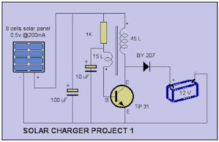
Simple Solar charger circuit

Simple Solar charger circuit to take advantage of sunlight shining on the earth can continue to be utilized to serve as a power source so that we can at least save on electricity prices continuing to rise, below is one of a series of simple power plant can be created and used to fill your motorcycle battery or for emergency lights.

The circuit scheme of Solar Power Generation
 
Simple Solar charger circuit
 
Sunlight is received by the solar panels are then processed into electricity, but electricity generated from each panel is still too small where the 8 Cell Panel arranged in series only mrnghasilkan voltage of approximately 4 volts with a current 200 mA.
nah therefore required an electronic circuit to increase the voltage and current enough to be used as a Battery Charger.
Electronic Rainmaking act as a series of DC to DC Inverter (DC to DC Inverter), which was built by two pieces of Capacitor, Resistor 1, a transistor, a diode, and a coil which is the point of the creation of this series.

The circuit was built with a single oscillator system (blocking oscillator) which was built by the transistor and a coil in which the primary winding totaling 45 turns and 15 turns in the secondary as feedback to provide the voltage at the base of the transistor output of the primary winding connected to the diode and used to The battery charging.

When the circuit is coupled with the Emergency Neon Lights will certainly get enough voltage to light at night for free. because its batteries during the day in charge by the sun.

The success of this experiment is a way of making a coil which is the same way with the topic of emergency fluorescent lights
.
List of Components
  • 8 cell 0.5v 200 mA solar panel (sold in many electronics stores) or make use of solar panels used a calculator that is damaged / not used anymore you dismantle it and take solarcell
  • Capacitor 100 UF
  • Capacitor 10 UF
  • Transistor TIP 31 or similar
  • Resistor 1 K
  • Diode BY 207 (Diada 5 Ampere) or similar
  • Accu Motor.
  • Approximately 3 meters of 0.25 mm diameter wire email.>
  • Ferite rods are frequently used in radio-AM radio.
 
Read More..

6V 12V Constant Current Battery Charger Circuit PCB Layout Added

The circuit diagram of the charger shown in Fig.1 is centered around the L200 type voltage regulator IC, which ensures constant charging voltage to any connected 6V, 12V battery.
R2 and R3 are the current limiting resistors. The charging current is selected by altering the values of R2 and R3. Strictly, the necessity of R2 holds good if the charging current exceeds 500 mA. The current required for charging is obtained by the relation: l(charging) = 0.45(R2+R3)/ R2R3

The circuit diagram and PCB layout of the above explained 6V 12V constant current battery charger is shown below:


Read More..

Sunday, September 21, 2014

Solar Charger for Lead Acid Batteries

This circuit is still under development, but works well as shown.

This circuit is intended for charging lead-acid batteries with a solar panel. The customary diode that prevents the battery from discharging through the solar panel has been replaced by a FET-comparator combination. The charger will stop charging once a pre-set voltage (temperature compensated) has been reached, and recommence charging when the voltage has dropped off sufficiently. The load is disconnected when the baterry voltage drops below 11V and reconnected when it gets back to 12.5V.

The circuit has the following features:

  •     Charges until Vbat = 13,8V (adjustable), then float charges;
  •     Shuts down load when Vbat <11v (adjustable), resets at 12,5v;
  •     Temperature compensation;
  •     Will work with cheap and readily available components like LM393 comparators and BUZ11 FETs;
  •     Uses less than 1.3mA (Attempts to use micropower comparators have failed spectacularly so far, see below);
  •     Burns less than 20mW in FETs when charging at 0,5A. (More expensive FETs with a lower RDSON will yield even better results).
  • Note that the charging current is limited only by the solar panel used.

    Heres the circuit:

    Solar

    Note the funny place of grounding of the first 2 comparators. Theres some weirdness here: this bit of the circuit gives me headaches. Two problems:

    •     If I ground the first two comparators (LM393) in the same place as the third, i.e. not between the FETs, the thing wont work and the battery will discharge over the solar panel. Why? Am I playing to close to the rails? How can this be remedied/improved/redesigned? Do I need a diode between the comparators imputs?
    •     If I use micropower comparators like the Texas Instruments TLC393, the comparators blow up spectacularly, but with the standard LM393 everything works fine. Why? What did I miss?

    Help would be greatly appreciated!

    Next attempt

    This one works fine and uses about 0.5mA, but that might improve because Im not done tweeking yet:

    Solar

    by Oscar den Uijl, odu@xs4all.nl

Read More..

Monday, September 8, 2014

Mobile Cellphone Battery Charger

Charging of the mobile phone battery is a huge issue while traveling as power supply source is not usually available. In case you keep your mobile phone switched on continuously, its battery will go flat within to six hours, making the mobile phone useless. A fully charged battery becomes necessary when your distance from the nearest relay station increases. Here is a simple charger that replenishes the mobile phone battery within to hours. Fundamentally, the charger is a current-limited voltage source. Usually, mobile phone battery packs need three.6-6V DC & 180-200mA current for charging. These usually contain NiCd cells, each having one.2V rating. Current of 100mA is for charging the mobile phone battery at a slow rate. A 12V battery containing eight pen cells gives sufficient current (one.8A) to charge the battery connected across the output terminals.

Diagram  of cellphone charger

The schema also monitors the voltage level of the battery. It automatically cuts off the charging system when its output terminal voltage increases above the predetermined voltage level. Timer IC NE555 is used to charge & monitor the voltage level in the battery. Control voltage pin five of IC1 is supplied with a reference voltage of five.6V by zen-er diode ZD1. Threshold pin 6 is supplied with a voltage set by VR1 & trigger pin two is supplied with a voltage set by VR2. When the discharged mobile phone battery is connected to the schema, the voltage given to trigger pin two of IC1 is below 1/3Vcc & hence the flip-flop in the IC is switched on to take output pin three high.


When the battery is fully charged, the output terminal voltage increases the voltage at pin two of IC1 above the trigger point threshold. This switches off the flip-flop & the output goes low to terminate the charging method. Threshold pin 6 of IC1 is referenced at 2/3Vcc set by VR1. Transistor T1 is used to enhance the charging current. Value of R3 is critical in providing the necessary current for charging. With the given value of 39-ohm the charging current is around 180 mA.

The schema can be constructed on a tiny general-purpose PCB. For calibration of cut-off voltage level, use a variable DC power source. Connect the output terminals of the schema to the variable power supply set at 7V. Fine-tune VR1 in the middle position & slowly fine-tune VR2 until LED1 goes off, indicating low output. LED1 ought to turn on when the voltage of the variable power supply reduces below 5V. Enclose the schema in a tiny plastic case & use suitable connector for connecting to the cell phone battery.
Read More..

Sunday, September 7, 2014

USB Charger For Lithium Ion battery

USB
USB Battery Charger For Lithium Ion battery with the LM3622 is a series of lithium ion battery charger. This charger circuit operates using power from the USB source PC.
Read more
Read More..

Thursday, August 28, 2014

Variable charger circuit

Indeed the accu charger circuit , the voltage required must be in accordance with voltage batteries , such accu 12 volts the the output voltage should not be above 12 volts and 12 volts should not be too down. If it does not comply with the required voltage , it will make the batteries or accu quickly broken. But not to worry to find the right voltage to charge to accu, the voltage control circuit is equipped to facilitate in determining the voltage.
Transformer
Primary : 33 turns #22
Secondary : 45 turns #22
Core : Ferroxcube 203 F 181.3C3
Read More..

Wednesday, August 27, 2014

Portable Battery Charger Circuit

This circuit was designed to charge Nicad battery packs in the range of 4.8 to 15.6 V from a convenient remote power source , such as automobile battery. When power is first applied to the circuit applied to the circuit , a small bias current supplied by R1 via winding L1 , starts to turn on the transistor TR1.
portable
This forces a voltage across L2 and the positive feedback given by the coupling of L1 and L2 causes the transistor to turn hard on , applying the full supply across L2. The base drive voltage induced across L1 makes the junction the necessary base current to hold Q1 on.
Component List

Resistor
R1 = 1M
R2 = 120R
R3 = 10R
R4 = 39R

Capacitor
C1 = 100uF 25V
C2 = 0.01uF
C3 = 4700pF
C4 = 100uF 25V

Diode
D1 = 1N4148
D2 = BYV27-5
D3 = BYV27-5

Transistor
Q1 = ZTX650

Transformer
L1 = 12T 36awg
L2 = 13T 36awg
L3 = 20T 30awg
L4 = 40T 30awg
Core FX3437 with gap of 0.08mm
Former DT2492
Read More..

USB powered battery charger circuit

rangkaian
At this time I will share about the series used in the usb to charge battery. Issued voltage 4.7 Volt to 5 Volt DC suitable for battery charge the phone, as well as other batteries. 


Below is a circuit where the voltage is removed the usb on the computer will be strengthened by several components so that the voltage used to charge batteries more powerful and filtered, and will make it more durable and long lasting.
USB
Part List :
R1 = 1 K
R2 = 330 R
R3 = 4K7
R4 = 300 R
R5 = 27R
D1 = 4.7 volt zener /1W
C1 = 100uF/16V
Q1 = BC548
Q2 = BC558A
Read More..

Sunday, August 17, 2014

Car battery charger with MC78T12

Car battery charger with MC78T12 circuit

It is a very simple circuit that can be used to charge car batteries. In this circuit there are facilities to control the charging current and voltage.

The circuit is based on The MC78T12ABT IC. IC is just a 7812 in TO-3 package capable of 3A. The transformer T1 steps down the mains voltage and the diodes D1 and D2 does the work of rectification. The capacitor C1 and C2 is the filter acts as a decoupling capacitor.

The ground terminal of IC1 is raised to 2.1V with the diodes D3, D4 and D5. So the output of IC1 is regulated 14.1V (12 2.1). The battery is recharged through diode D6 D6.The blocks the reverse flow of current from the battery to the load circuit when the voltage is not available. Metro M1 shows the load current and M2 shows the load voltage.
Read More..

Tuesday, August 12, 2014

Broken Charger connection Alert


The above schema can be useful to detect if the load of any battery charger or plug-in adaptor supply is not properly connected. The load can be a set of batteries to be charged or any other type of battery or low dc voltage operated device.The schema can safely operate over a 3 to 15V range and 1A max. current, provided the supply voltage is about one volt higher than the voltage required by the load.


Charge Alert


Parts:
R1______________10K 1/4W Resistor R2_______________1K 1/4W Resistor R3_______________1K 1/4W Resistor (Optional, see Notes) D1,D2________1N4007 1000V 1A Diodes D3______________LED Red (Optional, see Notes) Q1,Q2_________BC557 45V 100mA PNP Transistors BZ1___________Piezo sounder (incorporating 3KHz oscillator) The schema is inserted between the supply and the load, therefore, until a trickle-charging current of at least 100µA is flowing towards the load, D1 and D2 will conduct. The forward voltage drop (about 1V) available across the Diodes, drives Q2 into conduction and, consequently, Q1 will be cut-off. If no appreciable load is connected across the diagram output, Q2 will become cut-off, Q1 will conduct and the Piezo-sounder will beep. Notes: * An optional LED and its series limiting resistor can be wired in parallel to BZ1, as shown in dotted lines in the schema diagram. * In this case you may omit the Piezo-sounder in order to obtain a visual alert only.
Read More..