Showing posts with label inverter. Show all posts

Monday, November 17, 2014

6 to 12 Volt Power Supply Inverter

This inverter circuit can provide up to 800mA of 12V power from a 6V supply. For example, you could run 12V car accessories in a 6V (British?) car. The circuit is simple, about 75% efficient and quite useful. By changing just a few components, you can also modify it for different voltages.


6
Part List:

R1, R4 2.2K 1/4W Resistor
R2, R3 4.7K 1/4W Resistor
R5 1K 1/4W Resistor
R6 1.5K 1/4W Resistor
R7 33K 1/4W Resistor
R8 10K 1/4W Resistor
C1,C2 0.1uF Ceramic Disc Capacitor
C3 470uF 25V Electrolytic Capcitor
D1 1N914 Diode
D2 1N4004 Diode
D3 12V 400mW Zener Diode
Q1, Q2, Q4 BC547 NPN Transistor
Q3 BD679 NPN Transistor
L1 See Notes
MISC Heatsink For Q3, Binding Posts (For Input/Output), Wire, Board
Read More..

Monday, November 3, 2014

12V Flourescent Lamp Inverter

Fluorescent tubes use far less energy than incandescent lamps and fluorescent tubes last a great deal longer as well. Other advantages are diffuse, glare-free lighting and low heat output. For these reasons, fluorescent lighting is the natural choice in commercial and retail buildings, workshops and factories. For battery-powered lighting, fluorescent lights are also the first choice because of their high efficiency. The main drawback with running fluorescent lights from battery power is that an inverter is required to drive the tubes.

12V Fluorescent Lamp Inverter Circuit diagram:

12-volt

Fig.1: two switch-mode circuits are involved here: the DC-DC inverter involving IC1, Q1 & Q2 and the fluoro tube driver which converts high voltage DC to AC via IC3 and Q3 & Q4 in a totem-pole circuit.
Inverter efficiency then becomes the major issue. There are many commercial 12V-operated fluorescent lamps available which use 15W and 20W tubes. However, it is rare to see one which drives them to full brilliance. For example, a typical commercial dual 20W fluorescent lamp operating from 12V draws 980mA or 11.8W. Ignoring losses in the fluorescent tube driver itself, it means that each tube is only supplied with 5.9W of power which is considerably less than their 20W rating. So while the lamps do use 20W tubes, the light output is well below par.

Warning:
This circuit generates in excess of 300V DC which could be lethal. Construction should only be attempted by those experimenced with mains-level voltages and safety procedures.
Read More..

Cheap 12V to 220V Inverter

Even though today’s electrical appliances are increasingly often self-powered, especially the portable ones you carry around when camping or holidaying in summer, you do still sometimes need a source of 230 V AC - and while we’re about it, why not at a frequency close to that of the mains? As long as the power required from such a source remains relatively low - here we’ve chosen 30 VA - it’s very easy to build an inverter with simple, cheap components that many electronics hobbyists may even already have.

Though it is possible to build a more powerful circuit, the complexity caused by the very heavy currents to be handled on the low-voltage side leads to circuits that would be out of place in this summer issue. Let’s not forget, for example, that just to get a meager 1 amp at 230 VAC, the battery primary side would have to handle more than 20 ADC!. The circuit diagram of our project is easy to follow. A classic 555 timer chip, identified as IC1, is configured as an astable multivibrator at a frequency close to 100 Hz, which can be adjusted accurately by means of potentiometer P1.

Cheap 12V to 220V Inverter Circuit diagram:

Inverter

As the mark/space ratio (duty factor) of the 555 output is a long way from being 1:1 (50%), it is used to drive a D-type flip-flop produced using a CMOS type 4013 IC. This produces perfect complementary square-wave signals (i.e. in antiphase) on its Q and Q outputs suitable for driving the output power transistors. As the output current available from the CMOS 4013 is very small, Darlington power transistors are used to arrive at the necessary output current. We have chosen MJ3001s from the now defunct Motorola (only as a semi-conductor manufacturer, of course!) which are cheap and readily available, but any equivalent power Darlington could be used.

These drive a 230 V to 2 × 9 V center-tapped transformer used ‘backwards’ to produce the 230 V output. The presence of the 230 VAC voltage is indicated by a neon light, while a VDR (voltage dependent resistor) type S10K250 or S07K250 clips off the spikes and surges that may appear at the transistor switching points. The output signal this circuit produces is approximately a square wave; only approximately, since it is somewhat distorted by passing through the transformer. Fortunately, it is suitable for the majority of electrical devices it is capable of supplying, whether they be light bulbs, small motors, or power supplies for electronic devices.

PCB layout:
invertor-circuit-diagram


Parts List :
Resistors
R1 = 18k?
R2 = 3k3
R3 = 1k
R4,R5 = 1k?5
R6 = VDR S10K250 (or S07K250)
P1 = 100 k potentiometer
Capacitors
C1 = 330nF
C2 = 1000 µF 25V
Semiconductor
T1,T2 = MJ3001
IC1 = 555
IC2 = 4013
Miscellaneous
LA1 = neon light 230 V
F1 = fuse, 5A
TR1 = mains transformer, 2x9V 40VA (see text)
4 solder pins

Note that, even though the circuit is intended and designed for powering by a car battery, i.e. from 12 V, the transformer is specified with a 9 V primary. But at full power you need to allow for a voltage drop of around 3 V between the collector and emitter of the power transistors. This relatively high saturation voltage is in fact a ‘shortcoming’ common to all devices in Darlington configuration, which actually consists of two transistors in one case. We’re suggesting a PCB design to make it easy to construct this project; as the component overlay shows, the PCB only carries the low-power, low-voltage components.

The Darlington transistors should be fitted onto a finned anodized aluminum heat-sink using the standard insulating accessories of mica washers and shouldered washers, as their collectors are connected to the metal cans and would otherwise be short-circuited. An output power of 30 VA implies a current consumption of the order of 3 A from the 12 V battery at the ‘primary side’. So the wires connecting the collectors of the MJ3001s [1] T1 and T2 to the transformer primary, the emitters of T1 and T2 to the battery negative terminal, and the battery positive terminal to the transformer primary will need to have a minimum cross-sectional area of 2 mm2 so as to minimize voltage drop.

The transformer can be any 230 V to 2 × 9 V type, with an E/I iron core or toroidal, rated at around 40 VA. Properly constructed on the board shown here, the circuit should work at once, the only adjustment being to set the output to a frequency of 50 Hz with P1. You should keep in minds that the frequency stability of the 555 is fairly poor by today’s standards, so you shouldn’t rely on it to drive your radio-alarm correctly – but is such a device very useful or indeed desirable to have on holiday anyway? Watch out too for the fact that the output voltage of this inverter is just as dangerous as the mains from your domestic power sockets.

So you need to apply just the same safety rules! Also, the project should be enclosed in a sturdy ABS or diecast so no parts can be touched while in operation. The circuit should not be too difficult to adapt to other mains voltages or frequencies, for example 110 V, 115 V or 127 V, 60 Hz. The AC voltage requires a transformer with a different primary voltage (which here becomes the secondary), and the frequency, some adjusting of P1 and possibly minor changes to the values of timing components R1 and C1 on the 555.


Read More..

Friday, October 31, 2014

Inverter Circuit for Soldering Iron

The following inverter circuit can be used to supply soldering iron or other small electronic devices which need up to about 50W / 230V power supply.

Inverter


Transistors T1 and T2 (each BC547) form an astable multivibrator that creates 50Hz signal. The complementary outputs from the collectors of transistors T1 and T2 are fed to pnp Darlington driver stages formed by transistor pairs T3-T5 and T4-T6 (utilising BC558 and BD140). The outputs from the drivers are fed to transistors T7 and T8 (each and every 2N3055) connected for push-pull operation. Use suitable heat-sinks for transistors T5 via T8.

A 230V AC primary to 12V-0-12V, 4.5A secondary transformer (X1) is utilised. The centre-tapped terminal of the secondary of the transformer is connected to the battery (12V, 7Ah), whilst the other two terminals of the secondary are connected to the collectors of power transistors T7 and T8, respectively.

Whenever you power the circuit making use of switch S1, transformer X1 produces 230V AC at its primary terminal. This voltage could be employed to heat your soldering iron.

Build the circuit on a standard purpose PCB and place it in a suitable cabinet. Hook up the battery and transformer with proper current-carrying wires. On the front panel of the box, fit power switch S1 along with a 3-pin socket for connecting the soldering iron.

Note that the ratings of the battery, transistors T7 and T8, and transformer could vary as these all depend on the load (soldering iron).
Read More..

Monday, October 20, 2014

New 100W Inverter 12VDC to 220VAC circuit diagram

The following diagram is an inverter circuit which will give you 220V AC 50Hz with maximum power of 100W. This inverter built using transistors both the square wave generator and the amplifier.The Q1 and Q2 used generate square wave. Q5-Q8 amplify the signal and the transformer to increase the AC/square wave current from 12VAC to 220V AC 50HZ.

100W Inverter 12VDC to 220VAC circuit diagram

100W Inverter 12VDC to 220VAC circuit diagram


Inverter PCB layout


Read More..

Simle DC to AC Inverter by IC 555

This be basic AC inverter Circuit. Convenient for the initiator who have to is extremely fond of something experience. Because of use IC 555 highly popular, perform produce the frequency ,then enlarge with transistor NPN and PNP number TIP41 and TIP42 drive the coil transformer. Get by can pay Voltage output about 120V to 230V at frequency 50Hz. By have R4 perform control the frequency and should use. Voltage supply about 5V to 15V the detail sees in circuit picture sir. Link


Read More..

Friday, October 17, 2014

Build a100W Inverter 12V to 220V Circuit Diagram

How to Build a100W Inverter 12V to 220V Circuit Diagram. When use the electric appliances that want 220V AC 50HZ, which have small-sized about 100Watt not exceed. By when you apply outside home, as a result have to have Mini power inverter about 100Watt, perform modify from work electricity forces of battery 12V give tall fair the work. 

100W Inverter 12V to 220V Circuit Diagram
 
100W
 If you are New user electronics or want to economize or want to build electronics project use by oneself. I begs for to advise this circuit , because it uses , transistor number BC557 or the number replaces, perform oscillator generator. Then have power transistor 2N3055 numbers perform to drive coil transformer for converter voltage give tall go up 220V AC 50HZ at the electric power about 100 watt not exceed. When apply to transformer about 2A-3A. Picture circuit detail and like model PCB Board.

 PCB


Read More..

Friday, September 26, 2014

Inverter Voltage Wave Circuit Diagram

This circuit voltage inverter was designed using common electronic components, it produces a negative voltage from a positive. It is very simple, its operation is reasonable and can be used in different utilities in electronics where one has to inverts tensions of a wave.

Inverter Voltage Wave Circuit Diagram


Inverter Voltage Wave Circuit Diagram

Read More..

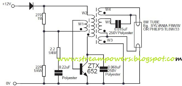
8W Fluorescent Lamp Inverter based ZTX652 Circuit Diagram

This circuit is basically a 8W inverter circuit. The  circuit continues to be intended to drive an 8W fluorescent lamp from a 12V power supply, utilizing an cheap inverter primarily based on a ZTX652 transistor.

The inverter will operate from supplies in the variety of 10V to 16.5V, obtaining efficiencies up to 78% as a result causing it suitable for use in on-charge devices like as caravans / mobile homes / RVs and also periodically charged devices like as roadside lamps, camping lights or outhouse lights etc. Other capabilities on the inverter are that it oscillates at an inaudible 20kHz and that it contains reverse polarity protection.


 8W Fluorescent Lamp Inverter based ZTX652 Circuit Diagram


 8W Fluorescent Lamp Inverter based ZTX652 Circuit Diagram


 Download the 8W fluorescent lamp inverter application note:
» Download Link
Download the ZTX652 datasheet:
» Download Link
Read More..

Monday, September 22, 2014

500W low cost 12V to 220V inverter circuit and explanation

Using this circuit you can convert the 12V dc in to the 220V Ac. In this circuit 4047 is use to generate the square wave of 50hz and amplify the current and then amplify the voltage by using the step transformer.


author: Ashad Mustufa
e-mail: mustufa66@hotmail.com
web site: http://www.electronics-lab.com

Circuit diagram

How to calculate transformer rating
The basic formula is P=VI and between input output of the transformer we have Power input = Power output
For example if we want a 220W output at 220V then we need 1A at the output. Then at the input we must have at least 18.3V at 12V because: 12V*18.3 = 220v*1
So you have to wind the step up transformer 12v to 220v but input winding must be capable to bear 20A.


Read More..

Wednesday, September 3, 2014

230 Volt AC To Inverter Switching Wiring diagram Schematic


Description

                  Before three weeks i am introduced  inverter schema diagram but the schema not included ac to inverter switching part so today i introducing a 230 Volt Ac to inverer switching schema diagram .

Circuit showing a inverter switching  . Here i have used  bc 558 ,BC 548 and a relay for making this schema . 230 volt connected to the base of the transistor Q1.When the power is ON positive volt coming to the base of the transistor so the relay schema is open and load working in 230 V AC .When the power is OFF ground voltage coming to the base of the transistor so the Base of the Q2 is positive there for the   relay schema closed and load working in inverter input .Part list and applications are showing below. 

Part List

Component No: Value  Usage
R1 100KΩ Emitter Load
R2 10K Ω Base Biasing 
R3180KΩ  Current Limiting 
Q1BC558  Switching  
Q2BC548   Switching 
D1 IN4007   Relay Balancing 
RL112 V  Inverter Switching 
Read More..

Monday, September 1, 2014

230 Volt AC To Inverter Switching Wiring diagram Schematic

230

Description
Before three weeks i am introduced  inverter schema diagram but the schema not included ac to inverter switching part so today i introducing a 230 Volt Ac to inverer switching schema diagram .
Circuit showing a inverter switching  . Here i have used  bc 558 ,BC 548 and a relay for making this schema . 230 volt connected to the base of the transistor Q1.When the power is ON positive volt coming to the base of the transistor so the relay schema is open and load working in 230 V AC .When the power is OFF ground voltage coming to the base of the transistor so the Base of the Q2 is positive there for the relay schema closed and load working in inverter input .Part list and applications are showing below. Link

Part List

Component No: Value  Usage
R1 100KΩ Emitter Load
R2 10K Ω Base Biasing 
R3180KΩ  Current Limiting 
Q1BC558  Switching  
Q2BC548   Switching 
D1 IN4007   Relay Balancing 
RL112 V  Inverter Switching 
Read More..

Friday, August 29, 2014

555 DC to AC inverter circuit diagram


This is inverter schema diagram.Here I have used famous Transistors TIP41 and TIP42.And the frequency is generated by NE555.By using R4 you can control the frequency.out put voltage is 120V-230V.the frequency is 50Hz.This schema operates with 5V-15V.


Note

# Be careful because you are dealing with 230V.

#This schema is not suitable for kids.

#Use heat sinks for transistors
Read More..

Wednesday, August 13, 2014

Simple 1000W Power Inverter circuit diagram

This is the power inverter schema based MOSFET RFP50N06. The inverter capable to handle loads up to 1000W, it’s depended on your power inverter transformer. The RFP50N06 Fets are rated at 50 Amps and 60 Volts. Heatsink is required for cooling the MOSFETs. You may add some MOSFETs with parallel connection to get more power. It is recommended to have a “Fuse” in the Power Line and to always have a “Load connected”, while power is being applied.

 Simple 1000W Power Inverter schema diagram

Simple 1000W Power Inverter schema diagram

Read More..