Showing posts with label phone. Show all posts
Showing posts with label phone. Show all posts
Saturday, November 15, 2014
GSM CELL PHONE JAMMER CIRCUIT
This is Simple GSM Cell Phone Jammer Circuit Diagram. A “Cell Jammer” is just way of saying “Dirty Transmitter” which happens to transmit within the Cellular Phone Bands. Reality is, the dirtier the better. GSM Cell Phones works on 900/1800 Mhz frequency. GSM-900 and GSM-1800 are used in most of the world.
Circuit Diagram

Working
- The 555 timer [8 pin] IC simply makes a noise. It’s coupled via C4 [electrolytic] to modulate the MRF transistor oscillator. With C1 set at roughly 1/3rd, you will be close to 900 MHz. By sweeping the C1 trimmer capacitor, you can swing the output frequency from 800 MHz to 2 GHz with the transistor and values shown above.
- You could replace the 555 chip with an electret microphone and listen to yourself talk on a scanner, so the unit could easily couple as a UHF Bug.
- Instead of a single Tapped Coil, I’ve used two molded inductors for ease of construction. Values for C1, C2, L1 , L2 are critical for the frequency range.
- You might want to build the unit into a metal box, add an on/off switch in the batteries + line, and maybe even add a LED. Connect an old 800 MHz cell phone antenna to C5.
- Would you believe the whole thing can be built on top of the 555 IC itself when using surface mount components, and the lot will fit onto a nine volt battery clip. Output is reasonably good, although the current drain is a bit high, so a new 9 Volt battery will only run about an hour .
- This circuit works on 10-15 metres of range.

Sunday, November 2, 2014
5V DC REGULATED PHONE CHARGER ELECTRONIC DIAGRAM

5V DC REGULATED PHONE CHARGER ELECTRONIC DIAGRAM
Regulated phone charger which is used as an emergency charger for mobile phones with source from ordinary batteries, and works with 1.5V input DC voltage. At 5V, it can provide output to 70mA. If the current is drawn, the voltage will be drop. A006 microcontroller is used to create square wave which used to drive the Field Effect Transistor BBV93.
Thursday, September 25, 2014
Make this Cell Phone Jammer Circuit at Home
A “Cell Jammer” is actually technique of pointing out a “Nuisance RF Maker” which just might happen to get distributed within the Cellular Phone Bands. Certainty is, the dirtier the more beneficial.
The 555 timer IC purely renders a noise. It’s hooked via C4 to modulate the MRF transistor oscillator. With C1 fixed at about 1/3rd, you will be in close proximity to nine hundred MHz. By cleaning the C1 trimmer capacitor, you could fluctuate the output frequency from 800 MHz to 2 GHz with the transistor and values presented.
You may substitute the 555 chip with an electret microphone and tune in to by yourself lecture on a scanner, thus the product could very well duo as a UHF Bug.
Rather than one particular Tapped Coil, I’ve used a couple of plastic inductors for simple structure.Values for C1,C2,L1,L2 are fundamental for the frequency range.

You may perhaps build the component into a metallic box, add an on/off control in the dc batteries + track, and possibly bring in a LED. Connect a well used eight hundred MHz cellphone antenna to C5.
Do you believe the whole item could be produced on the top of the 555 IC itself when utilizing surface mount parts, and the lot will probably hold onto a 9 volt battery snap. Output is moderately sound, though the current draw is a tad bit substantial, so a brand new 9 Volt battery will simply manage in the vicinity of one hour,.
The “Cell Kill Distance” is around 10 – 15 ft, sufficient for most grounds.
The 555 timer IC purely renders a noise. It’s hooked via C4 to modulate the MRF transistor oscillator. With C1 fixed at about 1/3rd, you will be in close proximity to nine hundred MHz. By cleaning the C1 trimmer capacitor, you could fluctuate the output frequency from 800 MHz to 2 GHz with the transistor and values presented.
You may substitute the 555 chip with an electret microphone and tune in to by yourself lecture on a scanner, thus the product could very well duo as a UHF Bug.
Rather than one particular Tapped Coil, I’ve used a couple of plastic inductors for simple structure.Values for C1,C2,L1,L2 are fundamental for the frequency range.
You may perhaps build the component into a metallic box, add an on/off control in the dc batteries + track, and possibly bring in a LED. Connect a well used eight hundred MHz cellphone antenna to C5.
Do you believe the whole item could be produced on the top of the 555 IC itself when utilizing surface mount parts, and the lot will probably hold onto a 9 volt battery snap. Output is moderately sound, though the current draw is a tad bit substantial, so a brand new 9 Volt battery will simply manage in the vicinity of one hour,.
The “Cell Kill Distance” is around 10 – 15 ft, sufficient for most grounds.
Thursday, September 18, 2014
Reuse Old Mobile Phone Battery for LED lighting
Normally mobile batteries have a lifespan of 2-5 years under normal usage. But then we have to replace them. Nowadays there are cheap replacement batteries which cost no more than 1$. But these low cost batteries run only 6-12 months. What to do with the used batteries, which can’t be reused in mobiles? Well, easy solution is to use the batteries in a circuit that requires less current. We can use them for LED lighting.
Do you have old unusable Mobile battery?
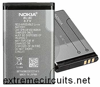
Normally mobile batteries have a lifespan of 2-5 years under normal usage. But then we have to replace them. Nowadays there are cheap replacement batteries which cost no more than 1$. But these low cost batteries run only 6-12 months. What to do with the used batteries, which can’t be reused in mobiles?Do you have old unusable Mobile battery?

Source by : http://www.extremecircuits.net/2012/08/hacks-and-mods-reuse-old-mobile-phone.html
Mobile phone Circuits to Get Even smaller
Transceivers, appliances such as mobile phones that can send and receive messages, have become smaller and smaller over the last few years, but users are about to experience a new meaning in miniaturisation.
Research at The Hong Kong University of Science & Technology (HKUST) has successfully combined a unique system architecture and new circuit design techniques to reduce them in size like never before.
Research at The Hong Kong University of Science & Technology (HKUST) has successfully combined a unique system architecture and new circuit design techniques to reduce them in size like never before.

The transformation applies to the CMOS (Complimentary Metal-Oxide Semiconductor) manufacturing process, which can produce integrated circuits and systems with the highest integration level at the lowest cost. Applying new techniques to the CMOS process, Dr Luong’s research enables many “off-chip” components to be combined to realize a system-on-chip. “But,” he said, “this integration created great challenges in circuit implementation.” Part of the research was to solve the problems by new circuit design techniques.
“The system architecture and circuitry go hand in hand, he added. “They must both work, or neither will be useful.”
The resulting design gives the highest component integration in the smallest chip area ever reported, said Dr Luong.
In his design, all off-chip components are fitted into a central chip measuring 36 mm
 with packaging, and 8mm without being packaged.
 Dr Luong’s miniaturisation method means appliances will soon be made for even lower cost and lower power consumption in addition to being much smaller in size and lighter in weight.
“With the lowering of cost, size and power, many new and interesting applications will become possible and practical,” he said.
Low-power wireless transceivers, for example, could be integrated into implanted devices such as heart pacemakers to wirelessly transmit and receive information between patients and doctors or monitoring systems.
Wearable mobile phones as small as wrist watches at an affordable price could also become a reality.
Auther
Principal Investigator
Dr Howard Luong
Monday, August 25, 2014
Hold The Phone With Music
This is so useful schema for us Because If our caller is in hold on position we can allow them to listen a music.When you want to operate this schema you can hold on your phone and switch on the S1. The RED wire from the phone jack is typically positive and the GREEN wire is negative or ground.
Subscribe to:
Posts (Atom)
