Showing posts with label video. Show all posts

Wednesday, October 22, 2014

Splitter and Amplifier Video Circuit Diagram

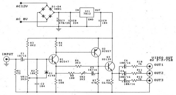
This is the video amplifier circuit with splitter, it is designed to amplify the video signal, compensating for the loss of signal because this signal will then be split up to three outputs. The output signals may be used in television monitors, recording at the same time several DVDs, etc. .. The advantage of this circuit is that it is quite cheap, easy to build and the results are very good.

Splitter and Amplifier Video Circuit Diagram

Splitter and Amplifier Video Circuit Diagram

The video amplifier circuit has a maximum gain ratio of only 4 times the impedance is 75 ohms on the input and output, and wide bandwidth of this circuit is 5 Mhz

adjust VR1
1. Adjusting VR1 until the voltage at the base of Q1 is equal to one volt. And is the voltage drop across R7. (No input signal). Approximately 0.75 volts.
2. Adjust VR1 in the middle Enter the input signal is 1 Vp-p, then adjust VR2 to have the lowest rate of increase.
Then turn on the TV or monitor to the output and then adjust VR1 until the test signal to be applied without distortion.

PCB

Splitter and Amplifier Video Circuit Diagram PCB
 
Read More..

Monday, October 20, 2014

3 Input Video MUX Cable

The circuit diagram shows a low-cost 3-input video MUX cable driver. In this circuit, the amplifier is loaded by the sum of RF and RG of each disabled amplifier. Resistor values have been chosen to keep the total back termination at 75 Ω while maintaining a gain of 1 at the 75-Ω load. The switching time between any two channels is approximately 32 ns when both enable pins are driven. When designing a circuit board for this cable driver, care should be taken to minimize trace lengths at the inverting input. The ground plane should also be pulled away from RF and RG on both sides of the board to minimize stray capacitance. Current consumption of the cable driver is a modest 8mA.
3-Input Video MUX Cable Driverw


Read More..

Thursday, September 18, 2014

The Audio Video Distribution Amplifier

With the amount of equipment in home entertainment centers today the need to be able to vary the gain of the audio or video signal is needed. I found this particular circuit helpful when used in conjunction with the Universal Descrambler and a Stabilizer circuit I built for making copies of video tapes. It not only allowed me the ability to fine tune the video strength it also helped me increase the recorded audio which typically becomes poor when making tape copies. Circuit operation is straight forward for amplifier circuits. The second channel for the audio amplifier is made up of the same components except the other half of IC1 is used. Pin 6 & 5 are inputs and 7 is the output.

Circuit Diagram
Read More..

Monday, August 25, 2014

Pioneer Video Bypass

Since the high demand for the Pioneer parking brake bypass; I have decided to come up with a easy diagram for you to follow which will allow you to play videos while you are in motion.

1.  Connect the blue system turn on (Remote) wire to spade #85 (If you have or installing and amplifier connect your amplifier turn on (Remote) wire to this prong also)

2. Connect a grounding wire to spade # 87 which jumps and connects to spade # 86. Then connect the wire to a good ground.

3. Connect the parking brake wire from the head unit (Green Wire) to spade # 30

4. Finish installing your stereo and enjoy your video.


Read More..