Showing posts with label lamp. Show all posts
Showing posts with label lamp. Show all posts
Monday, November 3, 2014
12V Flourescent Lamp Inverter
Fluorescent tubes use far less energy than incandescent lamps and fluorescent tubes last a great deal longer as well. Other advantages are diffuse, glare-free lighting and low heat output. For these reasons, fluorescent lighting is the natural choice in commercial and retail buildings, workshops and factories. For battery-powered lighting, fluorescent lights are also the first choice because of their high efficiency. The main drawback with running fluorescent lights from battery power is that an inverter is required to drive the tubes.
12V Fluorescent Lamp Inverter Circuit diagram:

Fig.1: two switch-mode circuits are involved here: the DC-DC inverter involving IC1, Q1 & Q2 and the fluoro tube driver which converts high voltage DC to AC via IC3 and Q3 & Q4 in a totem-pole circuit.
Inverter efficiency then becomes the major issue. There are many commercial 12V-operated fluorescent lamps available which use 15W and 20W tubes. However, it is rare to see one which drives them to full brilliance. For example, a typical commercial dual 20W fluorescent lamp operating from 12V draws 980mA or 11.8W. Ignoring losses in the fluorescent tube driver itself, it means that each tube is only supplied with 5.9W of power which is considerably less than their 20W rating. So while the lamps do use 20W tubes, the light output is well below par.
Warning:
This circuit generates in excess of 300V DC which could be lethal. Construction should only be attempted by those experimenced with mains-level voltages and safety procedures.

Saturday, October 18, 2014
Build a Varying Brightness AC Lamp Circuit
Varying Brightness AC Lamp Circuit, an SCR is used to slowly vary the intensity of a 120 volt light bulb by controlling the time that the AC line voltage is applied to the lamp during each half cycle.
Varying Brightness AC Lamp Circuit Diagram

Caution:
The circuit is directly connected to the AC power line and should be placed inside an enclosure that will prevent direct contact with any of the components. To avoid electrical shock, do not touch any part of the circuit while it is connected to the AC power line. A 2K, 10 watt power resistor is used to drop the line voltage down to 9 volts DC. This resistor will dissipate about 7 watts and needs some ventilation.
Operation:
A couple NPN transistors are used to detect the beginning of each half cycle and trigger a delay timer which in turn triggers the SCR at the end of the delay time. The delay time is established by a current source which is controlled by a 4017 decade counter. The first count (pin 3) sets the current to a minimum which corresponds to about 7 milliseconds of delay, or most of the half cycle time so that the lamp is almost off. Full brightness is obtained on the sixth count (pin 1) which is not connected so that the current will be maximum and provide a minimum delay and trigger the SCR near the beginning of the cycle. The remaining 8 counts increment the brightness 4 steps up and 4 steps down between maximum and minimum. Each step up or down provides about twice or half the power, so that the intensity appears to change linearly. The brightness of each step can be adjusted with the 4 resistors (4.3K, 4.7K, 5.6K, 7.5K) connected to the counter outputs.
The circuit has been built by Don Warkentien (WODEW) who suggsted adding a small 47uF capacitor from ground to the junction of the current source transistor (PNP) to reduce the digital stepping effect so the lamp will brighten and fade in a smoother fashion. The value of this capacitor will depend on the 4017 counting rate, a faster rate would require a smaller capacitor.
Friday, September 26, 2014
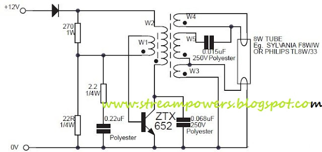
8W Fluorescent Lamp Inverter based ZTX652 Circuit Diagram
This circuit is basically a 8W inverter circuit. The circuit continues to be intended to drive an 8W fluorescent lamp from a 12V power supply, utilizing an cheap inverter primarily based on a ZTX652 transistor.
The inverter will operate from supplies in the variety of 10V to 16.5V, obtaining efficiencies up to 78% as a result causing it suitable for use in on-charge devices like as caravans / mobile homes / RVs and also periodically charged devices like as roadside lamps, camping lights or outhouse lights etc. Other capabilities on the inverter are that it oscillates at an inaudible 20kHz and that it contains reverse polarity protection.
8W Fluorescent Lamp Inverter based ZTX652 Circuit Diagram
Download the 8W fluorescent lamp inverter application note:
» Download Link
Download the ZTX652 datasheet:
» Download Link
Tuesday, August 26, 2014
Battery Powered Night Lamp
This schema is usable as a Night Lamp when a wall mains socket is not available to plug-in an ever running small neon lamp device. In order to ensure minimum battery consumption, one 1.5V cell is used and simple voltage doublers drives a pulsating ultra-bright LED: current drawing is less than 500µA. An optional Photo resistor will switch-off the schema in daylight or when room lamps illuminate, allowing further current economy. This device will run for about 3 months continuously on an ordinary AA sized cell or for around 6 months on an alkaline type cell but, adding the Photo resistor schemary, running time will be doubled or, very likely, triplicates. IC1 generates a square wave at about 4 Hz frequencies. C2 & D2 form voltage doublers, necessary to raise the battery voltage to a peak value able to drive the LED.
Parts:
R1 = 1M
R2 = 1M
R3 = 47K
R4 = LDR
C1 = 100nF-63V
C2 = 220uF-25V
D1 = Ultra Bright 10mm LED
D2 = 1N5819 B1 = 1.5V Battery or AA Cell
IC1 = 7555 CMos Timer IC
Notes:
* IC1 must be a CMos type: only these devices can safely operate at 1.5V supply or less. * If you do not need Photo resistor operation, omit R3 & R4 and connect pin 4 of IC1 to positive supply. * Ordinary LEDs can be used, but light intensity will be poor. * An ordinary 1N4148 type diode can be used instead of the 1N5819 Schottky-barrier type diode, but LED intensity will be reduced due to the higher voltage drop. * Any Schottky-barrier type diode can be used in place of the 1N5819, e.g. the BAT46, rated @ 100V 150mA.
Sunday, August 10, 2014
2 Pin Automobile Indicator Lamp Flasher Circuit with Buzzer
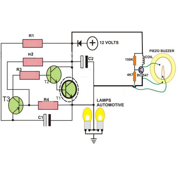
If you want to make a flasher unit for you motorbike then this schema is just for you. This simple turn signal flasher schema can be easily built and installed in any two wheelers for the desired actions. The schema employs just two 2-pins instead of 3 as found in other flasher diagram. Once installed, the schema will faithfully flash the side indicator lights whenever the intended function is switched ON. The schema also incorporates an optional buzzer schema which can be also included for getting a beeping sound in response to the flashing of the lamps.
Parts List
R1, R2, R3 = 10K
R4= 33K
T1 = D1351,
T2 = BC547,
T3 = BC557,
C1, C2 = 33uF.25V
L1 = Buzzer Coil
Subscribe to:
Posts (Atom)
