Showing posts with label 5v. Show all posts
Showing posts with label 5v. Show all posts
Sunday, November 2, 2014
5V DC REGULATED PHONE CHARGER ELECTRONIC DIAGRAM

5V DC REGULATED PHONE CHARGER ELECTRONIC DIAGRAM
Regulated phone charger which is used as an emergency charger for mobile phones with source from ordinary batteries, and works with 1.5V input DC voltage. At 5V, it can provide output to 70mA. If the current is drawn, the voltage will be drop. A006 microcontroller is used to create square wave which used to drive the Field Effect Transistor BBV93.

Thursday, October 23, 2014
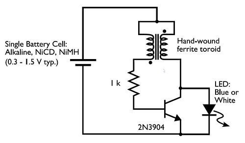
0 3 to 1 5V LED Flashlight

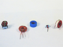
Its a little wisp of a circuit that allows you to drive a blue or white LED from a low voltage. Normally, if you want to light up a blue or white LED you need to provide it with 3 - 3.5 V, like from a 3 V lithium coin cell. But a 1.5 V battery like a AA cell simply will not work. But using the Joule Thief, it works like a charm. Not only does it work with a brand new battery, but it works until the battery is nearly dead-- down to 0.3 V. Thats well below the point where your other toys will tell you the battery is dead, so it can steal every last joule of energy from the battery (hence the name). To learn how to make one, watch the video, which is available in a variety of formats.


Simple 5V Regulated Power Supply Circuit Diagram
5V Regulated Power Supply Circuit Diagram is a small +5V power supply, which is useful when experimenting with digital electronics. Small inexpensive wall tranformers with variable output voltage are available from any electronics shop and supermarket. Those transformers are easily available, but usually their voltage regulation is very poor, which makes then not very usable for digital circuit experimenter unless a better regulation can be achieved in some way.
The following circuit is the answer to the problem. This circuit can give +5V output at about 150 mA current, but it can be increased to 1 A when good cooling is added to 7805 regulator chip. The circuit has overload and thermal protection. The capacitors must have enough high voltage rating to safely handle the input voltage feed to circuit. The circuit is very easy to build for example into a piece of veroboard.
The following circuit is the answer to the problem. This circuit can give +5V output at about 150 mA current, but it can be increased to 1 A when good cooling is added to 7805 regulator chip. The circuit has overload and thermal protection. The capacitors must have enough high voltage rating to safely handle the input voltage feed to circuit. The circuit is very easy to build for example into a piece of veroboard.

5V Regulated Power Supply Circuit Diagram
Parts:C1 = 100uF-25V electrolytic capacitor, at least 25V voltage rating
C2 = 10uF-25V electrolytic capacitor, at least 6-16V voltage rating
C3 = 100nF-63V ceramic or polyester capacitor
IC = 7805 regulator IC
ICs Pinout :
- Unregulated voltage in
- Ground (See Diagram)
- Regulated voltage out
Circuit features:
- Gives out well regulated +5V output, output current capability of 100 mA
- Built-in overheating protection shuts down output when regulator IC gets too hot
- Very simple and easy to build
- Very stable +5V output voltage, reliable operation
- Easy to get components, uses only very common basic components
- Based on datasheet example circuit, I have used this circuit succesfully as part of many electronics projects
- Part of electronics devices, small laboratory power supply
- Wide range of input unreglated DC 8-24V power supply
- Few dollars for the electronics components + the input transformer cost
Modification Iideas
More output current:
If you need more than 150 mA of output current, you can update the output current up to 1A doing the following modifications.
- Change the transformer from where you take the power to the circuit to a model which can give as much current as you need from output
- Put a heatsink to the 7805 regulator (so big that it does not overheat because of the extra losses in the regulator)
More output voltages:
If you need other voltages than +5V, you can modify the circuit by replacing the 7805 chips with another regulator with different output voltage from regulator 78xx chip family. The last numbers in the the chip code tells the output voltage. Remember that the input voltage muts be at least 3V greater than regulator output voltage ot otherwise the regulator does not work well.
Sunday, October 5, 2014
5V Regulator Ultra Low Power Circuit
5V Regulator Ultra Low-Power Circuit by http://www.extremecircuits.net
The accepted cesspool of the regulator is minute compared with that of, say, a 78L05: at an ascribe voltage of 9 V and open-circuit output, it is aloof beneath 50 µA. The ambit consists of a aboveboard bandgap advertence based on T1 and IC1, followed by an amplifier formed by IC2 and T1. The advertence voltage is about 1.22 V, which is aloft by IC2 to 5 V. The achievement voltage can be set to absolutely 5 V with P1. The ascribe voltage may lie amid 6.5 V and 30 V. The best achievement accepted with the present agreement and basic ethics as defined is about 10 mA. For optimum performance, T1a and T1b charge to be identical, which is why a bifold transtor Type MAT02 is used. Other types that may be acclimated are the MAT01, SSM2210 or LM394. In principle, two accepted BC transistors may be used, provided they are called for identical beginning voltage. Circuits IC1 and IC2 are programmable op amps Type OP22. In the case of IC2 this has the account that the aiguille achievement accepted can be set readily by altering the accumulation accepted to the op amp with R9. The akin of the accepted may be amid 500 nA and 400 µA.
Bear in apperception that a beyond achievement accepted requires the use of a added awful rated achievement transistor. Filter R6-C1 prevents any affected pulses extensive the ascribe of IC2. Capacitor C2 improves the adherence of the regulator, decidedly with best beating loading. Note that the ambit has a aerial resistance, so that it is appropriate to abode it in a buried asylum to anticipate causeless alluring and electromagnetic arrest actuality accompanying to the circuit. The regulator was activated with a absolute amount accepted of 1 mA on which was superimposed a square-wave accepted of 10 mA. The analysis after-effects are abbreviated in the table, in which Ig represents the accepted fatigued by the circuit.
Bear in apperception that a beyond achievement accepted requires the use of a added awful rated achievement transistor. Filter R6-C1 prevents any affected pulses extensive the ascribe of IC2. Capacitor C2 improves the adherence of the regulator, decidedly with best beating loading. Note that the ambit has a aerial resistance, so that it is appropriate to abode it in a buried asylum to anticipate causeless alluring and electromagnetic arrest actuality accompanying to the circuit. The regulator was activated with a absolute amount accepted of 1 mA on which was superimposed a square-wave accepted of 10 mA. The analysis after-effects are abbreviated in the table, in which Ig represents the accepted fatigued by the circuit.
2N3055 DC 12V to DC 6V 7 5V 9V Converter

This circuit is DC to DC converter model step down voltage. That can modify voltage input 12V DC from be DC 6V , 7.5V and 9V by have the size current about 1A – 2 Amp think. Be easy circuit use Zener diode maintain one’s position voltage. Be stable and have transistor 2N3055.
Thursday, September 18, 2014
Simple Low Drop 5V Regulator
A 4-cell pack is a convenient, popular battery size. Alkaline manganese batteries are sold in retail stores in packs of four, which usually provide sufficient energy to keep battery replacement frequency at a reasonable level. Generating 5 V from four batteries is, however, a bit tricky. A fresh set of four batteries has a terminal voltage of 6.4 V, but at the end of their life, this voltage is down to 3.2 V. Therefore, the voltage needs to be stepped up or down, depending on the state of the batteries. A flyback topology with a costly, custom designed transformer could be used, but the circuit in the diagram gets around the problem by using a flying capacitor together with a second inductor.
Circuit diagram:

The circuit also isolates the input from the output, allowing the output to go to 0 V during shutdown. The circuit can be divided conceptually into boost and buck sections. Inductor L1 and switch IC1 comprise the boost or step-up section, and inductor L2, diode D1 and capacitor C3 form the buck or step-down section. Capacitor C2 is charged to the input voltage, Vin, and acts as a level shift between the two sections. The switch toggles between ground and Vin+Vout , while the junction of L2, C2 and D1 toggles between –Vin and Vout +Vd1. Efficiency is directly related to the quality of the capacitors and inductors used.
Better quality capacitors are more expensive. Better quality inductors need not cost more, but normally take up more space. The Sanyo capacitors used in the prototype (C1–C3) specify a maximum ESR (effective series resistance) of 0.045 ½ and a maximum ripple current rating of 2.1 A. The inductors used specify a maximum DCR (direct current resistance) of 0.058 ½. Worst-case r.m.s. current through capacitor C2 occurs at minimum input voltage, that is, 400 mA at full load with an input voltage of 3 V.
Better quality capacitors are more expensive. Better quality inductors need not cost more, but normally take up more space. The Sanyo capacitors used in the prototype (C1–C3) specify a maximum ESR (effective series resistance) of 0.045 ½ and a maximum ripple current rating of 2.1 A. The inductors used specify a maximum DCR (direct current resistance) of 0.058 ½. Worst-case r.m.s. current through capacitor C2 occurs at minimum input voltage, that is, 400 mA at full load with an input voltage of 3 V.
Wednesday, September 10, 2014
4 5V To 12V DC

This ic 4.5V to 12V boost schema.You all can get lots of advantages through this schema.Here I have used famous IC LM2698.

Note
# input supply voltage range is 2.2V to 17V DC and outputs ranging from 2.2V to 17V DC
# IC can deliver only up to 400mA.So dont connect lodes more than that
# Build this schema on a PCB
Sunday, August 24, 2014
Simple Low Drop 5V Regulator
A 4-cell pack is a convenient, popular battery size. Alkaline manganese batteries are sold in retail stores in packs of four, which usually provide sufficient energy to keep battery replacement frequency at a reasonable level. Generating 5 V from four batteries is, however, a bit tricky. A fresh set of four batteries has a terminal voltage of 6.4 V, but at the end of their life, this voltage is down to 3.2 V. Therefore, the voltage needs to be stepped up or down, depending on the state of the batteries. A flyback topology with a costly, custom designed transformer could be used, but the schema in the diagram gets around the problem by using a flying capacitor together with a second inductor.
Simple Low-Drop 5V Regulator Circuit diagram:
The schema also isolates the input from the output, allowing the output to go to 0 V during shutdown. The schema can be divided conceptually into boost and buck sections. Inductor L1 and switch IC1 comprise the boost or step-up section, and inductor L2, diode D1 and capacitor C3 form the buck or step-down section. Capacitor C2 is charged to the input voltage, Vin, and acts as a level shift between the two sections. The switch toggles between ground and Vin+Vout , while the junction of L2, C2 and D1 toggles between –Vin and Vout +Vd1. Efficiency is directly related to the quality of the capacitors and inductors used.
Better quality capacitors are more expensive. Better quality inductors need not cost more, but normally take up more space. The Sanyo capacitors used in the prototype (C1–C3) specify a maximum ESR (effective series resistance) of 0.045 ½ and a maximum ripple current rating of 2.1 A. The inductors used specify a maximum DCR (direct current resistance) of 0.058 ½. Worst-case r.m.s. current through capacitor C2 occurs at minimum input voltage, that is, 400 mA at full load with an input voltage of 3 V.
Better quality capacitors are more expensive. Better quality inductors need not cost more, but normally take up more space. The Sanyo capacitors used in the prototype (C1–C3) specify a maximum ESR (effective series resistance) of 0.045 ½ and a maximum ripple current rating of 2.1 A. The inductors used specify a maximum DCR (direct current resistance) of 0.058 ½. Worst-case r.m.s. current through capacitor C2 occurs at minimum input voltage, that is, 400 mA at full load with an input voltage of 3 V.
Subscribe to:
Posts (Atom)
