Showing posts with label Intensity. Show all posts
Showing posts with label Intensity. Show all posts
Saturday, October 11, 2014
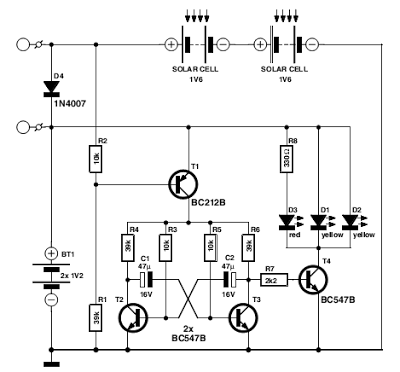
Flasher with LED high Intensity Circuit Diagram
This Flasher with LED high Intensity Circuit Diagram was designed as a flasher warning and was originally mounted on a bicycle. White LEDs are only recommended if the circuit is used as a bicycle front light and red LEDs only when used as a taillight. During the day, the two solar cells carry two 1.6 V AA batteries. In the darkness, the cell voltage disappears solar energy and batteries are automatically diverted to the circuit. The frequency of blinking (flashing) is about one per second.
Flasher with LED high Intensity Circuit Diagram
If you liked this article,Take a few Seconds to Share this and leave comments

Wednesday, September 24, 2014
LM317 Dispaly Intensity Controller Circuit
- When it detects a relatively high light intensity, the based and emitter voltage of T2 increase When the base voltage of Tz exceeds 2.7 Vj R4 limits the emitter voltage to 3.9V due to the constant current of 5.7 mA.
- This causes the voltage at the emitter of this pnp darlington transistor to be about LZVZ The voltage across Rs is the reference potential, 1.25 W of the Type LM3l7 regulator, so that lies about 5.7 mA, and the output voltage, UO, of the circuit is when T1 detects darkness.
- The maxi- mum output current is of the order of 700 mA when IC1 is adequately cooled. The input voltage range of the circuit is 8 to 15 VC
- This is a light dependent voltage source that regulates the supply to 7-segment dis- plays in accordance with the intensity of ambient light.
- The sensitivity of the regulator is adjustable with P1.
- T2 no longer conducts and the output voltage of the circuit is 5.7 L because the total resistance between the regulator output and ground is Rs+Ra+R4= 1,000 Q, and the current through it is still 5.7 mA.
- The regulating action is positive, a higher ambient light intensity results in the circuit raising the supply voltage to the displays. Phototransistor T1 does not conduct when it detects darkness, and the base of T2 is therefore grounded via R2 and Pt

Subscribe to:
Posts (Atom)
