Here is a Simple LED Volt meter to Monitor the charge level in Lead Acid Battery or Tubular battery. The terminal voltage of the battery is indicated through a four level LED indicators. The nominal terminal voltage of a Lead Acid battery is 13.8 volts and that of a Tubular battery is 14.8 volts when fully charged. The LED voltmeter uses four Zener diodes to light the LEDs at the precise breakdown voltage of the Zener diodes. Usually the Zener diode requires 1.6 volts in excess than its prescribed value to reach the breakdown threshold level. When the battery holds 13.6 volts or more, all the Zener breakdown and all LEDs light up. When the battery is discharged below 10.6 volts, all the LEDs remain dark. So depending on the terminal voltage of the battery, LEDs light up one by one or turns off.
Circuit diagram:Monday, November 3, 2014
SSL3250A PHOTO FLASH LED DRIVER ELECTRONIC DIAGRAM
These properties caused this device has long battery life and low power strain. Another features that this device has are protecting the battery and LED from overloading, trouble free operation such as overtemperature, over voltage, time-out function, undervoltage lockout, and feedback shorted protection.
Thursday, October 23, 2014
Make a series letters from the LED
Make a series letters from the LED , Things to consider before making the sign of the LED array,
1) Use LED nodes.
2) Paint the top of the PCB with a dark color (black).
3) Note the LED specifications. In this experiment use a 5mm diameter LED nodes
that emit red, specification voltage of 3 volts.
The assembly of LED:
1) One letter composed at most 5 columns and 7 rows.
2) One column mostly composed by 6 LEDs are arranged series.
3) Then the fifth column are connected in parallel.
Here is one letter LED scheme.
Medium picture below is the lay out of the 2-letter nameplate. To make the sign 8 letter, copied from a second stay this letter.
Example of LED on the letters A and B:
Read More..
1) Use LED nodes.
2) Paint the top of the PCB with a dark color (black).
3) Note the LED specifications. In this experiment use a 5mm diameter LED nodes
that emit red, specification voltage of 3 volts.
The assembly of LED:
1) One letter composed at most 5 columns and 7 rows.
2) One column mostly composed by 6 LEDs are arranged series.
3) Then the fifth column are connected in parallel.
4) Each column given the constraints, Rx, which amount depends on the number of LEDs in one column and depends also on the type of LED (in this experiment that used LED 5mm in diameter, clear with red light beam).
5) In a column consisting of 6 LEDs, Rx = 330 ohm, 5 LEDs, Rx = 560 Ohms, 4 LEDs, Rx = 680 Ohms Remember, this provision applies to 5 mm LED red light beam nodes.
6) Every letter was given FCS9013 transistor amplifier. Here is one letter LED scheme.
Medium picture below is the lay out of the 2-letter nameplate. To make the sign 8 letter, copied from a second stay this letter.
Example of LED on the letters A and B:
Value Rx in the first and the fifth column (letter A) of 560 ohms, because it consists of 5 LEDs are arranged series. Rx in the second column, third, and fourth, amounting to 680 ohms because it consists of two LEDs.
Rx first column letter B, 330 ohms. Rx second column, third, fourth, and fifth at 680 ohms.0 3 to 1 5V LED Flashlight

Its a little wisp of a circuit that allows you to drive a blue or white LED from a low voltage. Normally, if you want to light up a blue or white LED you need to provide it with 3 - 3.5 V, like from a 3 V lithium coin cell. But a 1.5 V battery like a AA cell simply will not work. But using the Joule Thief, it works like a charm. Not only does it work with a brand new battery, but it works until the battery is nearly dead-- down to 0.3 V. Thats well below the point where your other toys will tell you the battery is dead, so it can steal every last joule of energy from the battery (hence the name). To learn how to make one, watch the video, which is available in a variety of formats.


Wednesday, October 22, 2014
Build a LED Matrix Horizontally Circuit Diagram
LED Matrix Horizontally The circuit in this Models Idea shows an unconventional way to use a 5×7 LED matrix.You can use a design containing a set of 5×7 LED units without changing anything in the circuitry, except for the arrangement of the LED units.

Using one 5×7 LED matrix, or N units, horizontally instead of vertically allows the display of two characters, or 2×N characters. The minimum pattern for lowercase and uppercase letters requires only a 3×5 LED configuration, except for the letters M and m, which require at least a 5×5 LED configuration and need a dedicated subroutine.
The circuit in Figure 1 uses an 8-bit, 18-pin PIC microcontroller and a decade counter to drive one or two 5×7 LED units to provide a display module of two or four digits. The circuit uses a small pushbutton switch to increment the counter. By default, the circuit works in high-brightness mode. If you press the pushbutton during power-on, the circuit works in low-power mode.
Monday, October 20, 2014
LED DETECTS lightweight
All LEDs offer off lightweight of a specific color however some LEDs also are able to detect lightweight. clearly theyre not nearly as good as a tool that has been specially created to detect light; like solar cell, photocell, photo resistor, lightweight dependent resistor, photo transistor, photo diode and different photo sensitive devices.
A inexperienced LED can detect lightweight and a high-bright red LED can respond about a hundred times higher than a inexperienced LED, however the LED during this position in the circuit is classed as terribly high impedance and it needs a considerable quantity of amplification to show the detection into a worthwhile current-source. All different LEDs respond terribly poorly and arent price making an attempt. The accompanying circuit amplifies the output of the LED and permits it to be used for variety of applications.
The LED solely responds when the sunshine enters the tip of the LED and this makes it ideal for solar rackers and any time theres an outsized difference between the dark and light-weight conditions. itll not detect the
light in a very area unless the lamp is incredibly shut.

Saturday, October 11, 2014
Flasher with LED high Intensity Circuit Diagram
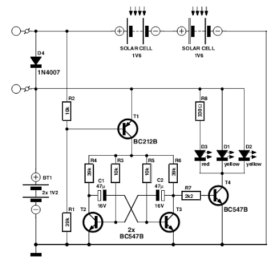
This Flasher with LED high Intensity Circuit Diagram was designed as a flasher warning and was originally mounted on a bicycle. White LEDs are only recommended if the circuit is used as a bicycle front light and red LEDs only when used as a taillight. During the day, the two solar cells carry two 1.6 V AA batteries. In the darkness, the cell voltage disappears solar energy and batteries are automatically diverted to the circuit. The frequency of blinking (flashing) is about one per second.
Flasher with LED high Intensity Circuit Diagram

If you liked this article,Take a few Seconds to Share this and leave comments
Thursday, September 18, 2014
Reuse Old Mobile Phone Battery for LED lighting
Normally mobile batteries have a lifespan of 2-5 years under normal usage. But then we have to replace them. Nowadays there are cheap replacement batteries which cost no more than 1$. But these low cost batteries run only 6-12 months. What to do with the used batteries, which can’t be reused in mobiles? Well, easy solution is to use the batteries in a circuit that requires less current. We can use them for LED lighting.
Do you have old unusable Mobile battery?

Normally mobile batteries have a lifespan of 2-5 years under normal usage. But then we have to replace them. Nowadays there are cheap replacement batteries which cost no more than 1$. But these low cost batteries run only 6-12 months. What to do with the used batteries, which can’t be reused in mobiles?Do you have old unusable Mobile battery?


Source by : http://www.extremecircuits.net/2012/08/hacks-and-mods-reuse-old-mobile-phone.html
Monday, September 15, 2014
HP LCD TV LT3700 LT4700 LED BLINKING CODES HOTEL MODE PANEL FAULTS
HP LT3200, LT3700, LT4200, LT4700 High-Definition LCD TV - LED Blinking Codes & Panel Faults - Hotel Mode _ Software version


Special condition to watch out for with the following message: Red LED blinking 2 sec interval – Digital Demodulator does not respond.
Error code 003 (digital demodulator does not respond) requires source to be selected as “antenna” before the test is valid. If source is not antenna, it will always give you error code 003 because digital demodulator is not turned on until “antenna” source is selected.Software version information.
To access the software version information OSD:
1 Turn the TV on.
2 Press the Menu button.
3 From OSD, select Setup => Time.
4 Press the following keys: SAP/MTS => 7 => 7 => 7. The software version information displays on the lower right corner of the TV.
To run diagnostics
1 Power off the TV and pull disconnect the power cord.
2 Plug in the power cord while holding the power button on the TV (not▲on the remote). Hold the power button until a testing message appears. This may take up to 30 seconds.
3 Diagnostic tests begin.
To get back to normal TV operation after running diagnostics
1 After the diagnostic test finishes, power off the TV and disconnect the power cord.
2 Wait for about 30 seconds; and then plug the power cord back in. The TV returns to normal mode.Installation menu
The installation menu allows you to change default setting values of current input audio and video modes. For example, to change the picture settings for a component input, switch the TV source to component before entering this mode.
To access the Installation menu:
1 Turn the TV on.
2 On the remote, press the Menu button.
3 From the OSD, select Setup => Time.
4 If the TV is NOT in Hotel mode, press the following key sequences: SAP/MTS => 1 => 3 => 5.
5 If the TV is in Hotel mode, change input source to AV2, then press SOURCE=> 1 => 3 => 5.
Color adjustments in this menu apply to ALL modes (Cool, Standard, or Warm). If you want to adjust the color temperature of a single mode, you will need to adjust the White Balance settings in the Factory Menu.
Hotel mode
To access the installation menu:
1 Run the Setup wizard (or channel scan and time setup) through the main menu.
2 Access the install menu and change to HOTEL mode from Normal TV mode.
To access the installation menu:
1 Turn the TV on.
2 On the remote, press the Menu button.
3 From the OSD, select Setup => Time.
4 Press the following key sequences: SAP/MTS => 1 => 3 => 5.
To return to normal mode from Hotel mode:
1 On the remote, press the Menu button.
2 From the OSD, select Setup => Time.
3 Change input source to AV2, and then press SOURCE => 1 => 3 => 5.
Panel faults
Problem: Line
Solution: Change LCD panel.

Problem: Scrape on the LCD panel
Solution: Change LCD panel or change Polarizer
Problem: Mura (cloudiness)
Solution: Change LCD panel

Problem: LCD crack
Solution: Change LCD panel
Problem: Scrape on the LCD panel
Solution: Change LCD panel

Saturday, August 30, 2014
AC powered LED Indicator

This is an indicator you can use this schema with your Ac electronic items.Here I have used normal Led.Attach purple color connections to the AC line.I suppose this will be a wonderful schema for you.
Note
# This is not a good schema for kids Because here we use 230V So dont try to build this.
# Build this schema on a PCB
Friday, August 22, 2014
Programmable LED Flashers
These diagram were designed on request. Both feature a flashing LED that, after a preset number of flashes will illuminate steadily until P1 (Reset) will be pressed.

Parts:
R1______________10K 1/4W Resistor
R2_______________1M 1/4W Resistor
R3_______________1K 1/4W Resistor (See Notes)
C1_______________4µ7 25V Electrolytic Capacitor
C2______________10nF 63V Polyester Capacitor
D1___________1N4148 75V 150mA Diode
D2______________LED (Any dimension, shape or color)
IC1____________4060 14 stage ripple counter and oscillator IC
P1_____________SPST Pushbutton
SW1____________SPST Toggle or Slider Switch
B1______________3V to 15V Battery or dc power source (See Notes)
uses only one chip and can be useful if a not very precise number of flashes of the LED is needed before reverting to the steady-on state. In fact, connecting D1 Anode to different output pins of the IC, the steady-on state of the LED will be obtained after 2, 4, 8, 16 flashes and so on.
Connecting D1 Anode as shown, the LED will start flashing at about two times per second after power-on and will revert to the steady state after 8 flashes. P1 resets the schema and C1 automatically resets IC at power-on.
Connecting D1 Anode to pin #13 of IC1 the flashes will be 4; to pin #1 will be 16 etc.
The flashing frequency of the LED can be varied by changing the values of R2 and/or C2.
Notes:
* Circuits were tested at 9V supply, but they might work in the 3 - 15V dc supply range.
* The LED current limiting resistor value was calculated for 9 - 12V supply and should be changed to suit different supply voltages.
Read More..
Parts:
R1______________10K 1/4W Resistor
R2_______________1M 1/4W Resistor
R3_______________1K 1/4W Resistor (See Notes)
C1_______________4µ7 25V Electrolytic Capacitor
C2______________10nF 63V Polyester Capacitor
D1___________1N4148 75V 150mA Diode
D2______________LED (Any dimension, shape or color)
IC1____________4060 14 stage ripple counter and oscillator IC
P1_____________SPST Pushbutton
SW1____________SPST Toggle or Slider Switch
B1______________3V to 15V Battery or dc power source (See Notes)
uses only one chip and can be useful if a not very precise number of flashes of the LED is needed before reverting to the steady-on state. In fact, connecting D1 Anode to different output pins of the IC, the steady-on state of the LED will be obtained after 2, 4, 8, 16 flashes and so on.
Connecting D1 Anode as shown, the LED will start flashing at about two times per second after power-on and will revert to the steady state after 8 flashes. P1 resets the schema and C1 automatically resets IC at power-on.
Connecting D1 Anode to pin #13 of IC1 the flashes will be 4; to pin #1 will be 16 etc.
The flashing frequency of the LED can be varied by changing the values of R2 and/or C2.
Notes:
* Circuits were tested at 9V supply, but they might work in the 3 - 15V dc supply range.
* The LED current limiting resistor value was calculated for 9 - 12V supply and should be changed to suit different supply voltages.
Monday, August 11, 2014
Long time LED Flasher circuit diagram

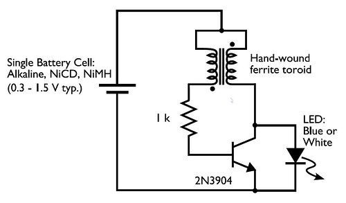
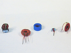
Today Im going to going to show you a very wonderful schema diagram .The special thing of this schema is this schema can light up a LED more than the normal time.Sometimes it will light up our LED more than one month.so I suppose this would be a good news for you guys.Here I have used very common Transistor 2N3904.When I was making this schema I turned about 20 turns around the toroid. the wire was a small schema wire.

Note
# Build this schema on a PCB
# Dont use more than 1.5V
Flashing LED Battery status Indicator
Signals when an on-schema battery is exhausted 5V to 12V operating voltage. A Battery-status Indicator schema can be useful, mainly to monitor portable Test-gear instruments and similar devices. LED D1 flashes to attire the users attention, signaling that the schema is running, so it will not be left on by mistake. The schema generates about two LED flashes per second, but the mean current drawing will be about 200µA. Transistors Q1 and Q2 are wired as an uncommon complementary astable multivibrator: both are off 99% of the time, saturating only when the LED illuminates, thus contributing to keep very low current consumption.
R2_____________120K 1/4W Resistor
R3_______________5K6 1/4W Resistor
R4_______________5K 1/2W Trimmer Cermet or Carbon
R5______________33K 1/4W Resistor
R6_____________680K 1/4W Resistor
R8_____________100K 1/4W Resistor
R9_____________180R 1/4W Resistor
C1,C2____________4µ7 25V Electrolytic Capacitors
D1____________BAT46 100V 150mA Schottky-barrier Diode
D2______________LED Red 5mm.
Q1____________BC547 45V 100mA NPN Transistor
Q2____________BC557 45V 100mA PNP Transistor
B1_______________5V to 12V Battery supply
Notes :
Streampowers
Flashing-LED Battery-status Indicator Circuit diagram :
Flashing-LED Battery-status Indicator Circuit Diagram
The schema will work with battery supply voltages in the 5 - 12V range and the LED flashing can be stopped at the desired battery voltage (comprised in the 4.8 - 9V value) by adjusting Trimmer R4. This range can be modified by changing R3 and/or R4 value slightly.
When the battery voltage approaches the exhausting value, the LED flashing frequency will fall suddenly to alert the user. Obviously, when the battery voltage has fallen below this value, the LED will remain permanently off. To keep stable the exhausting voltage value, diode D1 was added to compensate Q1 Base-Emitter junction changes in temperature. The use of a Schottky-barrier device (e.g. BAT46, 1N5819 and the like) for D1 is mandatory: the schema will not work if a common silicon diode like the 1N4148 is used in its place.
Parts :
R1,R7__________220R 1/4W Resistors R2_____________120K 1/4W Resistor
R3_______________5K6 1/4W Resistor
R4_______________5K 1/2W Trimmer Cermet or Carbon
R5______________33K 1/4W Resistor
R6_____________680K 1/4W Resistor
R8_____________100K 1/4W Resistor
R9_____________180R 1/4W Resistor
C1,C2____________4µ7 25V Electrolytic Capacitors
D1____________BAT46 100V 150mA Schottky-barrier Diode
D2______________LED Red 5mm.
Q1____________BC547 45V 100mA NPN Transistor
Q2____________BC557 45V 100mA PNP Transistor
B1_______________5V to 12V Battery supply
Notes :
- Mean current drawing of the schema can be reduced further on by raising R1, R7 and R9 values.
Streampowers
Subscribe to:
Posts (Atom)