Showing posts with label Make. Show all posts
Showing posts with label Make. Show all posts
Thursday, October 23, 2014
Make a series letters from the LED
Make a series letters from the LED , Things to consider before making the sign of the LED array,
1) Use LED nodes.
2) Paint the top of the PCB with a dark color (black).
3) Note the LED specifications. In this experiment use a 5mm diameter LED nodes
that emit red, specification voltage of 3 volts.
The assembly of LED:
1) One letter composed at most 5 columns and 7 rows.
2) One column mostly composed by 6 LEDs are arranged series.
3) Then the fifth column are connected in parallel.
Here is one letter LED scheme.
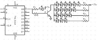
Medium picture below is the lay out of the 2-letter nameplate. To make the sign 8 letter, copied from a second stay this letter.

Example of LED on the letters A and B:

Read More..
1) Use LED nodes.
2) Paint the top of the PCB with a dark color (black).
3) Note the LED specifications. In this experiment use a 5mm diameter LED nodes
that emit red, specification voltage of 3 volts.
The assembly of LED:
1) One letter composed at most 5 columns and 7 rows.
2) One column mostly composed by 6 LEDs are arranged series.
3) Then the fifth column are connected in parallel.
4) Each column given the constraints, Rx, which amount depends on the number of LEDs in one column and depends also on the type of LED (in this experiment that used LED 5mm in diameter, clear with red light beam).
5) In a column consisting of 6 LEDs, Rx = 330 ohm, 5 LEDs, Rx = 560 Ohms, 4 LEDs, Rx = 680 Ohms Remember, this provision applies to 5 mm LED red light beam nodes.
6) Every letter was given FCS9013 transistor amplifier. Here is one letter LED scheme.

Medium picture below is the lay out of the 2-letter nameplate. To make the sign 8 letter, copied from a second stay this letter.

Example of LED on the letters A and B:
Value Rx in the first and the fifth column (letter A) of 560 ohms, because it consists of 5 LEDs are arranged series. Rx in the second column, third, and fourth, amounting to 680 ohms because it consists of two LEDs.
Rx first column letter B, 330 ohms. Rx second column, third, fourth, and fifth at 680 ohms.
Friday, September 26, 2014
How to Design and Make Transformer at Home
Almost every electronic circuit needs a separate power supply, which may be a battery or a rectified power supply. Here we will deal with the design and making of small transformers that are normally used in conjunction with mains-operated power supplies.
This will help electronic hobbyists to design and construct their own transformers according to their needs. In the following pages, a simplified design procedure is given so as to obtain satisfactorily designed transformers. However, the design procedure is often a matter of trial and error.
The tables provided here cut calculations short and help the designer to choose the proper size of wire or core lamination. Only relevant data and calculations are provided so that the designer is not confused by unnecessary details.
The transformer
A transformer has two or more windings of insulated copper wire over an iron core. They are: one primary winding and one or more secondary windings. Each winding is electrically isolated from the other, but they are magnetically coupled with the help of a laminated iron core. Small transforrners have a shell type construction, i.e. the windings are surrounded by the core as shown in Fig. 1. The power delivered by the secondary is actually transferred from the primary, but at a voltage level determined by the turns ratio of the two windings.
Making the Preliminary Transformer design
As the first step to the design of a transformer, the primary and secondary voltage ratings and the secondary current rating must be clearly stated. Then decide on the core material to be used: ordinary steel stampings or cold rolled grain oriented (CRGO) stampings. CRGO has a higher allowable flux density and lower losses.
Core area = 1.l52 x root of (Output voltage x output current) sq. cm.
For transformers with multiple secondaries, the sum of the output volt-amp. product of each winding is to be used. The number of tums on the primary and secondary windings is decided by the turns per volt ratio as:
Turns per volt = 1/ (4.44 X l0^-4 frequency x core area x flux density)
Here, the frequency is 50Hz for Indian domestic mains supply. The flux density can be taken as about 1.0 Weber/ sq. m. for ordinary steel stampings and about 1.3 Weber/ sq. m. for CRGO stampings.
Primary winding design
The current in the primary winding is given by:
Primary Current = Sum of (output volts x output amps)/(Primary volts x efficiency)
The efficiency of small transformers varies between 0.8 to 0.96. A value of 0.87 can be used for ordinary transformers. The proper wire size has to be selected for the winding. The wire diameter depends on the current to be supplied by the winding and the allowable current density of the wire. The current density may be as high as 233 amps/ sq. cm. in small transformers and as low as 155 amps/sq. cm. in large ones. Usually, a value of 200 amps/ sq. cm. can be taken, on whose basis Table 1 is given.
The number of tums in the primary winding is given by:
Primary turns = Turns per volt x primary volts.
The space taken up by the winding will depend on the insulation thickness, method of winding and the wire diameter. Table I gives the approximate values of the turns per square cm. from which we can estimate the window area occupied by the primary winding.
Primary Winding Area = Primary turns/Turns per sq. cm. from Table1
Secondary winding design
Since we have assumed that we know the secondary current rating, we can find out the wire size for the secondary winding by referring to Table 1 directly.
The number of turns on the secondary is calculated in the same way as for the primary, but about 3% extra turns are to be added to compensate for the internal drop of secondary voltage of the transformer, upon loading. Thus,
Secondary Turns = 1.03 (turns per volt x secondary volts)
The window area required for secondary winding is found from Table1 as
Secondary window area = Secondary Turns/Turns per sq. cm from Table1

Core size
The main criterion in selecting the core is the total window area of winding space available.
Total window area = Primary window area + sum of secondary window areas + space for former and insulation
Some extra area is required to accommodate the former and insulation between windings. The actual amount of extra area varies, although 30% may be taken to start with but may have to be modified later. The suitable core sizes having a larger window area are selected from Table ll. . Taking into account the gap between laminations while stacking them (the core stacking factor taken as 0.9), we have
Gross core area = Core Area/0.9 sq.cm.
ln general, a square central limb is preferred. For this, the width of the tongue of lamination is
Tongue width = root of Gross core area cm.
Now refer to Table ll again and finally select the proper i core size, with sufficient window area and a close value of the tongue width as calculated. Adjust the stack height as required to obtain the required core section.
Stack height = Gros core area/Actual tongue width cm.
The stack should not be much less than the tongue width but may be more. However, it should not be more than 1% times the tongue width.

How to Design and Make a Transformer finally
The windings are wound on an insulating former which .fits over the center limb of the core.The primary is usually wound first, then the secondary, with insulation between windings, A final insulating layer is provided over the windings to protect them from mechanical damage. When thin wires are used, their ends must be soldered to thicker wires for bringing the terminals outside the former. The laminations are assembled over the former with alternate laminations reversed in assembly. The laminations must be held together tightly by a suitable clamping frame or by screws (if holes are provided in the laminations).

Shield
lt is a good practice to use an electrostatic shield between the primary and secondary windings to prevent disturbances from passing through to the secondary from the primary. The shield is made out of a copper foil which is wound between the two windings for slightly over a tum. Insulation must be provided along the length of the foil and care taken so that the- two ends of the foil do not touch each other. A wire soldered to the foil is bought out and connected to the ground.

A practical design example can be witnessed below:

This will help electronic hobbyists to design and construct their own transformers according to their needs. In the following pages, a simplified design procedure is given so as to obtain satisfactorily designed transformers. However, the design procedure is often a matter of trial and error.
The tables provided here cut calculations short and help the designer to choose the proper size of wire or core lamination. Only relevant data and calculations are provided so that the designer is not confused by unnecessary details.
The transformer
A transformer has two or more windings of insulated copper wire over an iron core. They are: one primary winding and one or more secondary windings. Each winding is electrically isolated from the other, but they are magnetically coupled with the help of a laminated iron core. Small transforrners have a shell type construction, i.e. the windings are surrounded by the core as shown in Fig. 1. The power delivered by the secondary is actually transferred from the primary, but at a voltage level determined by the turns ratio of the two windings.
Making the Preliminary Transformer design
As the first step to the design of a transformer, the primary and secondary voltage ratings and the secondary current rating must be clearly stated. Then decide on the core material to be used: ordinary steel stampings or cold rolled grain oriented (CRGO) stampings. CRGO has a higher allowable flux density and lower losses.
Core area = 1.l52 x root of (Output voltage x output current) sq. cm.
For transformers with multiple secondaries, the sum of the output volt-amp. product of each winding is to be used. The number of tums on the primary and secondary windings is decided by the turns per volt ratio as:
Turns per volt = 1/ (4.44 X l0^-4 frequency x core area x flux density)
Here, the frequency is 50Hz for Indian domestic mains supply. The flux density can be taken as about 1.0 Weber/ sq. m. for ordinary steel stampings and about 1.3 Weber/ sq. m. for CRGO stampings.
Primary winding design
The current in the primary winding is given by:
Primary Current = Sum of (output volts x output amps)/(Primary volts x efficiency)
The efficiency of small transformers varies between 0.8 to 0.96. A value of 0.87 can be used for ordinary transformers. The proper wire size has to be selected for the winding. The wire diameter depends on the current to be supplied by the winding and the allowable current density of the wire. The current density may be as high as 233 amps/ sq. cm. in small transformers and as low as 155 amps/sq. cm. in large ones. Usually, a value of 200 amps/ sq. cm. can be taken, on whose basis Table 1 is given.
The number of tums in the primary winding is given by:
Primary turns = Turns per volt x primary volts.
The space taken up by the winding will depend on the insulation thickness, method of winding and the wire diameter. Table I gives the approximate values of the turns per square cm. from which we can estimate the window area occupied by the primary winding.
Primary Winding Area = Primary turns/Turns per sq. cm. from Table1
Secondary winding design
Since we have assumed that we know the secondary current rating, we can find out the wire size for the secondary winding by referring to Table 1 directly.
The number of turns on the secondary is calculated in the same way as for the primary, but about 3% extra turns are to be added to compensate for the internal drop of secondary voltage of the transformer, upon loading. Thus,
Secondary Turns = 1.03 (turns per volt x secondary volts)
The window area required for secondary winding is found from Table1 as
Secondary window area = Secondary Turns/Turns per sq. cm from Table1
Core size
The main criterion in selecting the core is the total window area of winding space available.
Total window area = Primary window area + sum of secondary window areas + space for former and insulation
Some extra area is required to accommodate the former and insulation between windings. The actual amount of extra area varies, although 30% may be taken to start with but may have to be modified later. The suitable core sizes having a larger window area are selected from Table ll. . Taking into account the gap between laminations while stacking them (the core stacking factor taken as 0.9), we have
Gross core area = Core Area/0.9 sq.cm.
ln general, a square central limb is preferred. For this, the width of the tongue of lamination is
Tongue width = root of Gross core area cm.
Now refer to Table ll again and finally select the proper i core size, with sufficient window area and a close value of the tongue width as calculated. Adjust the stack height as required to obtain the required core section.
Stack height = Gros core area/Actual tongue width cm.
The stack should not be much less than the tongue width but may be more. However, it should not be more than 1% times the tongue width.
How to Design and Make a Transformer finally
The windings are wound on an insulating former which .fits over the center limb of the core.The primary is usually wound first, then the secondary, with insulation between windings, A final insulating layer is provided over the windings to protect them from mechanical damage. When thin wires are used, their ends must be soldered to thicker wires for bringing the terminals outside the former. The laminations are assembled over the former with alternate laminations reversed in assembly. The laminations must be held together tightly by a suitable clamping frame or by screws (if holes are provided in the laminations).
Shield
lt is a good practice to use an electrostatic shield between the primary and secondary windings to prevent disturbances from passing through to the secondary from the primary. The shield is made out of a copper foil which is wound between the two windings for slightly over a tum. Insulation must be provided along the length of the foil and care taken so that the- two ends of the foil do not touch each other. A wire soldered to the foil is bought out and connected to the ground.
A practical design example can be witnessed below:
Thursday, September 25, 2014
Make this Cell Phone Jammer Circuit at Home
A “Cell Jammer” is actually technique of pointing out a “Nuisance RF Maker” which just might happen to get distributed within the Cellular Phone Bands. Certainty is, the dirtier the more beneficial.
The 555 timer IC purely renders a noise. It’s hooked via C4 to modulate the MRF transistor oscillator. With C1 fixed at about 1/3rd, you will be in close proximity to nine hundred MHz. By cleaning the C1 trimmer capacitor, you could fluctuate the output frequency from 800 MHz to 2 GHz with the transistor and values presented.
You may substitute the 555 chip with an electret microphone and tune in to by yourself lecture on a scanner, thus the product could very well duo as a UHF Bug.
Rather than one particular Tapped Coil, I’ve used a couple of plastic inductors for simple structure.Values for C1,C2,L1,L2 are fundamental for the frequency range.

You may perhaps build the component into a metallic box, add an on/off control in the dc batteries + track, and possibly bring in a LED. Connect a well used eight hundred MHz cellphone antenna to C5.
Do you believe the whole item could be produced on the top of the 555 IC itself when utilizing surface mount parts, and the lot will probably hold onto a 9 volt battery snap. Output is moderately sound, though the current draw is a tad bit substantial, so a brand new 9 Volt battery will simply manage in the vicinity of one hour,.
The “Cell Kill Distance” is around 10 – 15 ft, sufficient for most grounds.
The 555 timer IC purely renders a noise. It’s hooked via C4 to modulate the MRF transistor oscillator. With C1 fixed at about 1/3rd, you will be in close proximity to nine hundred MHz. By cleaning the C1 trimmer capacitor, you could fluctuate the output frequency from 800 MHz to 2 GHz with the transistor and values presented.
You may substitute the 555 chip with an electret microphone and tune in to by yourself lecture on a scanner, thus the product could very well duo as a UHF Bug.
Rather than one particular Tapped Coil, I’ve used a couple of plastic inductors for simple structure.Values for C1,C2,L1,L2 are fundamental for the frequency range.
You may perhaps build the component into a metallic box, add an on/off control in the dc batteries + track, and possibly bring in a LED. Connect a well used eight hundred MHz cellphone antenna to C5.
Do you believe the whole item could be produced on the top of the 555 IC itself when utilizing surface mount parts, and the lot will probably hold onto a 9 volt battery snap. Output is moderately sound, though the current draw is a tad bit substantial, so a brand new 9 Volt battery will simply manage in the vicinity of one hour,.
The “Cell Kill Distance” is around 10 – 15 ft, sufficient for most grounds.
Subscribe to:
Posts (Atom)
