Showing posts with label dual. Show all posts
Showing posts with label dual. Show all posts
Monday, October 20, 2014
Simple Dual Voltage Power Supply 12 Volt
This is the simple circuit diagram of Dual Voltage Power Supply. It is used for Misc… application. This circuit is called regulated power supply. For this reason the main component of this circuit is Regulator IC. It also needs few components to built. The regulator 7812 is the positive voltage regulator and 7912 is the negative voltage regulator.
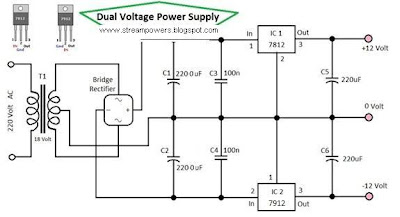
You can also use 7809 for 9 volt positive power supply and 7909 for negative voltage power supply. It regulates voltage from 24Volt to 12 Volt (DC). The transformer input is 110Volt to 220Volt (AC) and the output must be between 12Volt to 24Volt (AC) and current must be 500mA. In this circuit some capacitors are used as a filter for removing repole.

Saturday, October 18, 2014
LM7905 LM7805 Dual Variable Regulator power supply 5 25V
 When you want Dual power supply Variable Regulator be simple. I begs for to advise this circuit, because use the integrated circuit LM7805 and LM7905. Make have Voltage +5V to +25V and -5V to -25V unless. Still pay current get about 1A enough with general usability. The important factor is you should use Transformer at enough size doesn’t lower 2A and IC all stick let off the heat with. The detail is other see in circuit picture better sir.
Wednesday, September 24, 2014
Made Dual Regulated Power Supply

Notes:
In this circuit, the 7815 regulatates the positive supply, and the 7915 regulates the negative supply. The transformer should have a primary rating of 240/220 volts for europe, or 120 volts for North America. The centre tapped secondary coil should be rated about 18 volts at 1 amp or higher, allowing for losses in the regulator. An application for this type of circuit would be for a small regulated bench power supply.
In this circuit, the 7815 regulatates the positive supply, and the 7915 regulates the negative supply. The transformer should have a primary rating of 240/220 volts for europe, or 120 volts for North America. The centre tapped secondary coil should be rated about 18 volts at 1 amp or higher, allowing for losses in the regulator. An application for this type of circuit would be for a small regulated bench power supply.
Tuesday, September 23, 2014
Dual Power Supply 78xx 79xx series
This is a simple dual power supply using voltage regulator IC 78xx and 79xx series. Its the best and simplest choice for most non-critical applications. The 3 terminals are input, ground and output. The 78xx & 79xx series can provide up to 1A load current and it have onchip circuitry to prevent damage in the event of over heating or excessive current.
Dual Power Supply Schematic

This dual power supply project provides a dual power supply. With the appropriate choice of transformer and 3-terminal voltage regulator pairs you can easily build a small power supply delivering up to one amp at +/- 5V, +/- 9V, +/- 12V, +/- 15V or +/-18V. You have to provide the centre tapped transformer and the 3-terminal pair of regulators you want: 7805 & 7905, 7809 & 7909, 7812 & 7912, 7815 & 7915or 7818 & 7918.
Note that the + and - regulators do not have to be matched: you can for example, use a +5v and -9V pair. However, the positive regulator must be a 78xx regulator, and the negative a 79xx one. We have built in plenty of safety into this project so it should give many years of continuous service.
These protect mainly against any back emf which may come back into the power supply when it supplies power to inductive loads. They also provide additional short circuit protection in the case that the positive output is connected by accident to the negative output. If this happened the usual current limiting shutdown in each regulator may not work as intended. The diodes will short circuit in this case and protect the 2 regulators.
Dual Power Supply Parts

Read More..
Dual Power Supply Schematic
This dual power supply project provides a dual power supply. With the appropriate choice of transformer and 3-terminal voltage regulator pairs you can easily build a small power supply delivering up to one amp at +/- 5V, +/- 9V, +/- 12V, +/- 15V or +/-18V. You have to provide the centre tapped transformer and the 3-terminal pair of regulators you want: 7805 & 7905, 7809 & 7909, 7812 & 7912, 7815 & 7915or 7818 & 7918.
Note that the + and - regulators do not have to be matched: you can for example, use a +5v and -9V pair. However, the positive regulator must be a 78xx regulator, and the negative a 79xx one. We have built in plenty of safety into this project so it should give many years of continuous service.
These protect mainly against any back emf which may come back into the power supply when it supplies power to inductive loads. They also provide additional short circuit protection in the case that the positive output is connected by accident to the negative output. If this happened the usual current limiting shutdown in each regulator may not work as intended. The diodes will short circuit in this case and protect the 2 regulators.
Dual Power Supply Parts
Sunday, August 31, 2014
2x30W DUAL QUAD POWER AMPLIFIER FOR CAR RADIO TDA7377
Features:
- HIGH OUTPUT POWER CAPABILITY:
- 2 x 35W max./4Ω
- 2 x30W/4Ω EIAJ
- 2 x30W/4Ω EIAJ
- 2 x 20W/4Ω @14.4V, 1KHz, 10%
- 4 x 6W/4Ω @14.4V,1KHz, 10%
- 4 x 10W/2Ω @14.4V, 1KHz, 10%
- MINIMUM EXTERNAL COMPONENTS
- COUNT:
- – NO BOOTSTRAP CAPACITORS
- – NO BOUCHEROT CELLS
- – INTERNALLY FIXED GAIN (26dB BTL)
- ST-BY FUNCTION (CMOS COMPATIBLE)
- NOAUDIBLEPOPDURINGST-BYOPERATIONS
- DIAGNOSTICS FACILITY FOR:
- – CLIPPING
- – OUT TO GND SHORT
- – OUT TO VS SHORT
- – SOFT SHORT AT TURN-ON
- – THERMAL SHUTDOWN PROXIMITY
- Protections:
- OUPUT AC/DC SHORT CIRCUIT
- – TO GND
- – TO VS
- – ACROSS THE LOAD
- SOFT SHORT AT TURN-ON
- OVERRATING CHIP TEMPERATURE WITH
- SOFT THERMAL LIMITER
- LOAD DUMP VOLTAGE SURGE
- VERY INDUCTIVE LOADS
- FORTUITOUS OPEN GND
- REVERSED BATTERY
- ESD
Circuit Diagram:
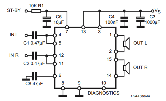 |
| 2x30W DUAL AMPLIFIER aplication circuit |
 |
| 2x30W QUAD AMPLIFIER aplication circuit |
Monday, August 11, 2014
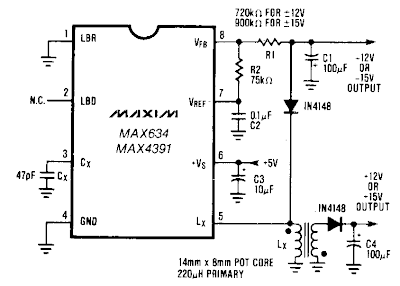
Dual Output dc dc Converter Wiring diagram Schematic
The Dual Output dc-dc Converter Circuit Diagram buck-boost configuration the MAX634 is well suited for dual output dc-dc converters. Only a second winding on the inductor is needed. Typically, this second winding is bifilar-primary and secondary are wound simultaneously using two wires in parallel.
The inductor core is usually a toroid or a pot core. The negative output voltage is fully regulated by the MAX634. The positive voltage is semi-regulated, and will vary slightly with load changes on either the positive or negative outputs.
Dual Output dc-dc Converter Circuit Diagram
Subscribe to:
Posts (Atom)
