Monday, August 11, 2014
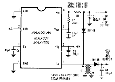
Dual Output dc dc Converter Wiring diagram Schematic
The Dual Output dc-dc Converter Circuit Diagram buck-boost configuration the MAX634 is well suited for dual output dc-dc converters. Only a second winding on the inductor is needed. Typically, this second winding is bifilar-primary and secondary are wound simultaneously using two wires in parallel.
The inductor core is usually a toroid or a pot core. The negative output voltage is fully regulated by the MAX634. The positive voltage is semi-regulated, and will vary slightly with load changes on either the positive or negative outputs.
Dual Output dc-dc Converter Circuit Diagram

Subscribe to:
Post Comments (Atom)
No comments:
Post a Comment