Showing posts with label control. Show all posts

Thursday, October 23, 2014

12 V Bidirectional Motor Control Circuit

This simple circuit drives DC motors with a maximum current of 1 A and can be built with readily available components.The output voltage is adjustable between 0 and 14 V and the polarity can be changed so that not only motor speed but also rotation direction can be adjusted by turning a knob. 

The circuit is also ideal as a controller for a DC model railway or small low voltage hobby tool. Power for the circuit is supplied by a 18 V mains transformer rated at 1.5 A. Diodes D1to D4 rectify the supply and capacitor C1 provides smoothing to give a DC output voltage of around 24 V. A classic ‘H’ bridge configuration is made up with transistors T1/T3 and T2/T4. Transistors T5 and T6 together with resistors R7 and R8 provide the current sense and limiting mechanism. The maximum output current limit can be changed from 1 A by using different value resistors for R7 and R8: IOUT = 0.6 V / R where R gives the value for R7 and R8. For increased current limit the mains transformer and diodes will need to be changed to cope with the extra current as well as the four transistors used in the bridge configuration. 

Circuit diagram:
12 V Bidirectional Motor Control Circuit Diagram  12 V Bidirectional Motor Control Circuit Diagram
 
Motor speed control and direction is controlled by a twin-ganged linear pot (P1). The two tracks of P1 together with R1/R2 and R3/R4 form two adjustable potential divider networks. Wiring to the track ends are reversed so that as the pot is turned the output voltage of one potential divider increases while the other decreases and vice versa. 

In the midway position both dividers are at the same voltage so there is no potential difference and the motor is stationary. As the pot is rotated the potential difference across the motor increases and it runs faster. The voltage drop across D5 and D6 is equal to the forward voltage drop VBE of the bridge transistors and ensures that the motor does not oscillate in the off position with the pot at its mid point.


http://www.ecircuitslab.com/2011/07/12-v-bidirectional-motor-control.html
Read More..

Saturday, October 18, 2014

Windshield Washer Control Automatic Diagram Circuit

Most, if not all, recent cars have an impressive amount of electronics, whether it be ABS brake systems, engine control with injection calculators, airbag activation, or other various functions, called comfort functions. Among them is one which we tend to forget because it has become so common today. It turns on the windshield wipers automatically for a few seconds after the windshield cleaner. This practice is almost indispensable because it avoids any dripping of excess rinse product right in the middle of a just-cleaned windshield.

Unfortunately, many ‘low end’ cars or some of the older cars are not equipped with this automatic function which is a very nice convenience to have. So, since all that is required is a handful of components that any electronics hobbyist worthy of the name already has in his/her drawer, we will discuss the circuit proposed here. This project is super simple and simply keeps the windshield wiper activated for a few seconds after the windshield washer control contact has been released.

While the windshield washer pump is operating, the 12 volts delivered by the battery are present at the terminals and are therefore charging capacitor C1. Once the windshield washer has stopped, this capacitor can only discharge through R2, P1, R3, and the T1 emitter-base junction, due to the presence of diode D1. It thus keeps T1 in the conductive state during a certain time, the exact period of which depends on the setting of P1. T1 in turn saturates T2, which then does the same for T3.

Circuit diagram:
Automatic Windshield Washer Controller Circuit Diagram

The Re1 relay is therefore connected which maintains the windshield wiper in operation because its work contact is wired in parallel to the control switch. Once C1 is sufficiently discharged, T1 is blocked, which then blocks T2 and T3 and deactivates relay Re1. The type of components is not really critical, even if we indicate specific reference numbers for T3, any low-power npn transistor with a gain over 25 will work. However, considering the amount of power consumed by the windshield wiper motor, relay Re1 will imperatively be an ‘automobile’ relay.

You can find very low-priced ones at many car accessory shops (and even at some component retailers). These relays maintain contact under 12 volts and often do not have more than one work contact but they are, in general, capable of cutting off about 20 amps. Finally, the only delicate point of this project is to properly identify the control wire for the windshield pump on one hand, and the windshield wiper motor on the other. Observing what is happening at the various connections with a simple voltmeter, should get it right without too much difficulty.
Author: Christian Tavernier
Copyright: Elektor Electronics
Read More..

Thursday, October 16, 2014

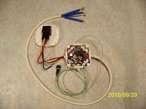
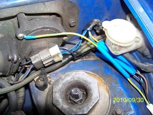
Hacking Car Wipers for Easy Control

How do you want to have your wipers become more intelligent? In this way, they could remember how frequent you need to use them. But of course, this will need the help of an ATmega8L micro-controller.

Hacks and Mods: Hacking Car Wipers for Easy Control

When you need to activate the wiper, you just press the button and it will run in one course. There is a 45 seconds waiting time that if you do not press the button, it will go on standby while telling itself that only one course is needed. The system will activate the wiper again if the button is pressed before 45 seconds. The good thing is that it will remember the interval when you pressed the button.

Hacks and Mods: Hacking Car Wipers for Easy Control
Read More..

How to Lights Control for Model Cars

The author gave his partner a radio controlled (RC) model car as a gif t. She found it a lot of fun, but thought that adding realistic lights would be a definite improvement. So the author went back to his shed, plugged in his soldering iron, and set to work equipping the car with realistic indicators, headlights, tail lights and brake lights.

Lights Control for Model Cars Circuit Diagram

The basic idea was to tap into the signal from the radio control receiver and, with a bit of help from a microcontroller, simulate indicators using flashing yellow LEDs and brake lights using red LEDs. Further red LEDs are used for the tail lights, and white LEDs for the headlights. Connectors JP4 and JP5 (channel 0) are wired in parallel, as are JP6 and JP7 (channel 1), allowing the circuit to be inserted into the servo control cables for the steering and drive motor respectively. The ATtiny45 micro-controller takes power from the radio receiver via diode D1. T1 and T2 buffer the servo signals to protect IC1’s inputs from damage. 
IC1 analyses the PWM servo signals and gen-erates suitable outputs to switch the LEDs via the driver transistors. T3 drives the two left indicators (yellow), T4 the two right indica-tors, and T5 the brake LEDs (red). The red tail lights (JP2-8 and JP2-8) and the white head-lights (JP2-9 and JP2-10) are lit continuously. The brake lights are driven with a full 20 mA, so that they are noticeably brighter than the tail lights, which only receive 5 mA. If you wish to combine the functions of tail light and brake light, saving t wo red LEDs, sim-ply connect pin 10 of JP2 to pin 14 and pin 12 to pin 16. Then connect the two combined brake/tail LEDs either at JP2-5 and JP2-6 or at JP2-7 and JP2-8.

JP3 is provided to allow the use of a separate lighting supply. This can either be connected to an additional four-cell battery pack or to the main supply for the drive motor. The val-ues given for resistors R8 to R17 are suitable for use with a 4.8 V supply. JP2 can take the form of a 2x10 header.

As usual the sof t ware is available as a free download from the Elektor web pages accom-panying this article[1], and ready-programmed microcontrollers are also available. The microcontroller must be taught what servo signals correspond to left and right turns, and to full throttle and full braking. First connect the fin-ished circuit to the radio control electronics in the car, making sure everything is switched of f. Fit jumper JP1 to enable configuration mode, switch on the radio control transmit-ter, set all proportional controls to their cen-tre positions, and then switch on the receiver. The indicator LEDs should first flash on both sides. Then the car will indicate left for 3 s: during this time quickly turn the steering on the radio control transmitter fully to the left and the throt tle to full reverse (maximum braking).

Hold the controls in this position until the car starts to indicate right. Then set the controls to their opposite extremes and hold them there until both sides flash again. Now, if the car has an internal combustion engine (and so cannot go in reverse), keep the throttle control on full; if the car has an electric motor, set the throttle to full reverse. Hold this position while both sides are flashing.  
Read More..

Friday, September 26, 2014

USB Enabled Remote Control

The objective of a remote control is to have the ability to operate a device from a certain distance. Nevertheless, remote controls usually are in places where we need to move around to find. This makes the remote totally useless as you may have used that time and energy to operate the device personally. If we take into account the limited reach that remote have, along with the fact that they are battery operated, we have an obsolete technology. All this can be fixed by developing a new remote control system.

Hacks and Mods: USB Enabled Remote Control
 
A lot of designs have been completed on systems that operate by clapping. But they have some disadvantages. Such as the fact that they work over only one sound or command. Another fact is that daily activities must be interrupted to give a command.

A whistling command system has been developed to control domestic devices. It works by detecting the sound peaks that are uniquely produced by whistles. Sound from each whistle is processed to give the order to the device.

The sound is received by a mic placed in the room. The microphone is connected to a USB device that transfers the information to a Linux operated computer. Once the command is recognized, the computer sends it to the device.
Read More..

Wednesday, September 24, 2014

UHF FM Remote Control Receiver Circuit

The receiver is intended primarily for use with the remote control UHF transmitter described in the preceding article. It is a super-regenerative type with an active RF amplifier, T1. The antenna signal is applied to the input inductor via a BNC socket, K1. The input circuit is tuned by trimmer C4. The amplified RF signal is applied to the input of the super-regenerative stage based on transistor T2. Although  the oscillator is, strictly speaking, not tuned, it will lock on to the amplified RF signal applied via coupling capacitor C7. The low-frequency modulation component is extracted from the oscillator signal with the aid of low-pass filter, R6-R7-C12-R8-C13. The signal level at the demodulator output is 50 to 800 mVpp, so that further amplification is required·before the signal can be applied to a digital input.  

The inductors in the RF amplifier input and output are made from 1 mm dia. silver-plated wire. The length of the pieces of wire is indicated by the component overlay. The wires run at a height of about 3 mm above the board surface. Note that the stator terminal of C4 is bent upwards and soldered direct to the input inductor. The same goes for junction C6-C7, which is soldered ‘in the air‘, directly op to the hot end of the inductor wire. Inductor L1 consists of 12 turns of 0.6-mm dia. enamelled copper wire. Its internal diameter is 3 mm. Each of chokes g and L3 consists of 4 turns of 0.2-mm dia enamelled copper wire through a 3 mm long ferrite bead. Capacitor C8 is a surface-mount technology (SMT) type which is fitted at the solder side of the board, as are the BFG65 and the BFQSO. The type indica- tion printed on the transistors is legible from the component side of the board. As indicated by the dashed lines on the component overlay, the super-regenerative section of the circuit must be screened from the rest. To do this, it is  best to solder a 20 mm high tin plate box on to the PCB as indicated.

For the transmitter circuit please CLICK HERE 


WebRep
currentVote
noRating
noWeight
Read More..

Thursday, September 18, 2014

Simple Telephone Record Control

This circuit will allow you to connect any tape recorder that has a mic and remote input to a phone line and automatically record both sides of a conversation when ever the phone is in use. You will need to take a couple of voltage readings before connecting the circuit. First determine the polarity of your phone line and connect it to the circuit as shown and then determine the polarity of the remote input and connect it to the circuit. Circuit operation is as follows. When the phone is on hook the voltage across the phone line is about 48volts dc. When the phone is off hook the voltage will drop to below 10volts dc. When the line voltage is at 48volts the FET is off which causes Q2 and Q3 to be off. When the phone is picked up the FET turns on along with Q2 and Q3 which turns your recorder on. The tape recorder must be in the record mode at all times. As you can see the power source for the circuit is the phone line.

Circuit Diagram

Read More..

Wednesday, September 17, 2014

Automatic Level Control Circuit

Description 

The rectifier input is tied to the input. This makes gain inversely proportional to input level so that a 20-dB drop in input level will produce a 20-dB increase in gain. The output will remain fixed at a constant level. The circuit will maintain an output level of 1 dB for an input range of +14 to -43 dB at 1 kHz.

Circuit Diagram 


Read More..

Wednesday, September 10, 2014

Digital Volume Control


This schema could be used for replacing your manual volume control in a stereo amplifier. In this schema, push-to-on switch SW1 controls the forward (volume increase) operation of both channels while a similar switch SW2 controls reverse (volume decrease) operation of both channels. A readily available IC from Dallas semiconductor, DS1669 is used here.


Parts:

J1 = RCA Audio Input Socket J2 = RCA Audio Input Socket C1 = 0.1uF-16V Ceramic Disc Capacitor C2 = 0.1uF-16V Ceramic Disc Capacitor C3 = 0.1uF-16V Ceramic Disc Capacitor IC1 = DS1669 (is available from Dallas SCo. SW1 = Momentary Push Button Switch SW1 = Momentary Push Button Switch

Notes:


* Replaces mechanical variable resistors. * Electronic interface provided for digital as well as manual control. * Wide differential input voltage range between 4.5 and 8 volts. * Wiper position is maintained in the absence of power. * Low-cost alternative to mechanical controls. * Applications include volume, tone, contrast, brightness, and dimmer control. * The schema is extremely simple and compact requiring very few external components. * The power supply can vary from 4.5V to 8V. * The input signal should not fall below -0.2 volts.

Read More..

Tuesday, September 9, 2014

Low Cost Tone Control Circuit

Low

This cheap tone control schema provides a maximum cut and boost of around 10dB at 10K and 50Hz. Two potensiometer used to control the high frequency (treble) and low frequency (bass).

The first BC109C transistor (left hand side) is acting as a buffer. It provides the schema with a high input impedance, around 250k has a voltage gain of slightly less than unity. As the Baxendall tone control schema is a passive design, all audio frequencies are attenuated. The position of the controls and reactance of the capacitors alters the audio response. The last transistor provides a slight boost of about 3x. The output is designed to feed an amplifier with input impedance of 10k to 250k. Both tone controls should be linear type potentiometers.
Read More..

Sunday, August 17, 2014

11W 11W AMPLIFIER WITH DC VOLUME CONTROL

General Description:

TDA7495 is a stereo 11+11W class AB power amplifier assembled in the @ Multiwatt 15 package, specially designed for high quality sound, TV applications. Features of the TDA7495 include linear volume control, Stand-by and mute functions.

Circuit Diagram:
TDA7495 circuit diagram


Read More..