Showing posts with label transistor. Show all posts
Showing posts with label transistor. Show all posts
Monday, October 20, 2014
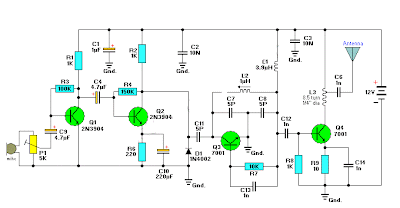
Build a 4 Transistor FM Transmitter Circuit Diagram
4 Transistor FM Transmitter Circuit Diagram

Build a 4 Transistor FM Transmitter Circuit Diagram. This 4 Transistor FM Transmitter Circuit Diagram provides an FM modulated signal with an output power of around 500mW. The input microphone pre-amp is built around a couple of 2N3904 transistors (Q1/Q2), and audio gain is limited by the 5k preset trim potentiometer.
The oscillator is a colpitt stage, frequency of oscillation governed by the tank circuit made from two 5pF ceramic capacitors and the L2 inductor. The output stage operates as a Class D amplifier, no direct bias is applied but the RF signal developed across the 3.9uH inductor is sufficient to drive this stage. The emitter resistor and 1k base resistor prevent instability and thermal runaway in this stage.
Labels:
4,
a,
build,
circuit,
diagram,
fm,
transistor,
transmitter
Friday, September 12, 2014
Electronic Transistor Turns Op Amp On or Off Wiring diagram Schematic
Build a Electronic Transistor Turns Op Amp On or Off Circuit Diagram. In this schema When transistor Q1 is switched off, the schema behaves as a voltage follower. By applying a positive voltage to the emitter of Q1 via a 10 KOhmhm resistor, the transistor is made to turn on and go into saturation. Thus, the lower end of R4 is connected to ground.
Electronic Transistor Turns Op Amp On or Off Circuit Diagram

The schema has not changed into that of a differential amplifier, except that the voltage difference is always 0 V. As long as the resistor ratios in the two branches around the op amp are in the same ratio, the output should be zero. A 47-KOhm resistor is used to null out any ratio errors so that the off attenuation is more than 60 dB. The high common-mode rejection ratio of a 741 enables this large attenuation to be obtained.
Labels:
amp,
circuit,
diagram,
electronic,
off,
on,
op,
or,
transistor,
turns
Subscribe to:
Posts (Atom)