Showing posts with label mains. Show all posts

Monday, September 1, 2014

Mains Frequency Monitor

Mains Frequency Monitor Circuit Diagram. Here is a simple frequency counter designed to monitor the 240VAC mains supply. It as a frequency range of 0-999Hz, so it could also be used with 400Hz equipment. Standard TTL/CMOS logic is employed for the counters and display drivers, while an ELM446 (IC1) generates accurate 1Hz pulses for gating. This device utilizes a 3.579545MHz crystal for its timebase, as commonly found in TV and video diagram and even on old PC motherboards.

Mains Frequency Monitor Circuit Diagram:

mains-frequency-monitor-schema
Mains Frequency Monitor Circuit Diagram


Copyright: Silicon Chip Electronics Magazine
Read More..

Wednesday, August 13, 2014

Mains Remote Alert

Pressing the pushbutton of the transmitter, a sound and/or light alert is activated in the receiver. The system uses no wiring or radio frequencies: the transmitted signal is conveyed into the mains supply line. It can be used at home, in any room from attic to cellar, simply plugging transmitter and receiver in the wall mains sockets. Transmission range can be very good, provided both units are connected to the mains supply within the control of the same light-meter.


Mains Remote-Alert Transmitter


Transmitter parts:


R1____________220K 1/4W Resistor
R2____________470R 1/2W Resistor
R3____________100K 1/4W Resistor
R4______________1K 1/4W Resistor

C1_____________10nF 400V Ceramic or Polyester Capacitor
C2____________330nF 400V Polyester Capacitor
C3______________1n5 63V Ceramic Capacitor (See Notes)
C4_____________10nF 63V Ceramic or Polyester Capacitor
C5____________100µF 25V Electrolytic Capacitor

D1,D2________1N4007 1000V 1A Diodes
D3_________BZX79C30 30V 500mW Zener Diode

Q1,Q2_________BC546 65V 100mA NPN Transistors

L1_______________IF Transformer for AM receivers, 445-470KHz

P1_____________SPST Mains suited Pushbutton

PL1____________Male Mains plug & cable


Receiver schema diagram:


Mains Remote-Alert Receiver


Receiver parts:

R1____________220K 1/4W Resistor
R2____________470R 1/2W Resistor
R3____________150K 1/4W Resistor
R4______________2K2 1/4W Resistor
R5____________100K 1/4W Resistor
R6_____________47K 1/4W Resistor
R7______________2K2 1/4W Resistor (Optional)

C1____________100nF 400V Polyester Capacitor
C2____________330nF 400V Polyester Capacitor
C3______________1n5 63V Ceramic Capacitor (See Notes)
C4,C6_________330pF 63V Ceramic Capacitors
C5,C7_________100µF 25V Electrolytic Capacitors

D1,D2________1N4007 1000V 1A Diodes
D3_________BZX79C12 12V 500mW Zener Diode
D4,D5,D6_____1N4148 75V 150mA Diodes
D7_____________5mm. Red LED (Optional)

Q1,Q2_________BC547 45V 100mA NPN Transistors

L1_______________IF Transformer for AM receivers, 445-470KHz

BZ1___________Piezo sounder (incorporating 3KHz oscillator)

PL1____________Male Mains plug & cable


Transmitter schema operation:

Q1 and Q2 are wired as a Darlington pair to obtain the highest possible output from a Hartley type oscillator running at about 135KHz frequency. The 230Vac mains is reduced to 30Vdc without the use of a transformer by means of C2 reactance, a two diode rectifier cell D1 & D2 and Zener diode D3.
The oscillator output is taken from L1 secondary winding and injected into the mains wiring by means of C1.

Receiver schema operation:

The 135KHz sinewave generated by the transmitter is picked-up from mains wiring by C1 and selected by the tuned schema L1-C3. Q1 greatly amplifies the incoming sinewave and converts it in a 12V-peak squarewave. D4 & D5 limit the input voltage at Q1 base to less than 1V-peak to avoid damaging of the transistor due to the high voltage transients frequently occurring on the mains line. D6 eliminates any negative component of the signal and Q2 drives the load. C7 is necessary to smooth the signal residues appearing across the load.
The 12Vdc supply for this unit is obtained as described above for the transmitter schema.

Notes:

* Transmitter and receiver coils L1s must be tuned regulating their ferrite cores to obtain maximum output at C3 leads, either in transmitter and receiver.
* This setup is better done using an oscilloscope and placing the two units as far as possible to each other.
* The tuning of the coils at 135KHz frequency should be obtained with the ferrite core almost totally inserted in its slot, if 455KHz IF transformers are used for both L1s.
* Using IF transformers different from those specified, a change in both C3s value could be needed. The value of these capacitors may vary from 1 to 3.3nF but must be the same in transmitter and receiver.
* The load can be a beeper, a LED or both. Omitting the beeper and choosing the LED as the only load, its limiting resistor R7 should be reduced in value to about 1K, to increase device brightness. In this case, a 10mm. diameter LED type or greater, can also be useful .
* Warning! These units are connected to 230Vac mains, then some parts in the schema boards are subjected to lethal potential! Avoid touching the diagram when plugged and enclose them in plastic boxes.


Read More..

Saturday, August 9, 2014

Mains Manager Wiring diagram Schematic

Very often we forget to switch off the peripherals like monitor, scanner, and printer while switching off our PC. The problem is that there are separate power switches to turn the peripherals off. Normally, the peripherals are connected to a single of those four-way trailing sockets that are plugged into a single wall socket. If that socket is accessible, all the devices could be switched off from there and none of the equipment used will require any modification. 

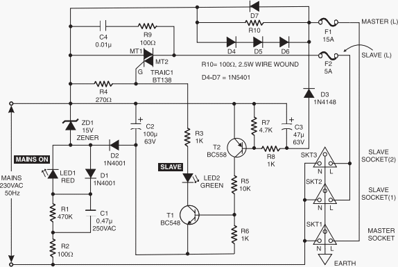
Here is a mains manager schema that allows you to turn all the equipment on or off by just operating the switch on any one of the devices; for example, when you switch off your PC, the monitor as well as other equipment will get powered down automatically. You may choose the main equipment to control other gadgets. 

The main equipment is to be directly plugged into the master socket, while all other equipment are to be connected via the slave socket. The mains supply from the wall socket is to be connected to the input of the mains manager schema. The unit operates by sensing the current drawn by the control equipment/load from the master socket. On sensing that the control equipment is on, it powers up the other (slave) sockets.

The load on the master socket can be anywhere between 20 VA and 500 VA, while the load on the slave sockets can be 60 VA to 1200 VA. During the positive half cycle of the mains AC supply, diodes D4, D5, and D6 have a voltage drop of about 1.8 volts when current is drawn from the master socket. Diode D7 carries the current during negative half cycles. Capacitor C3, in series with diode D3, is connected across the diode combination of D4 through D6, in addition to diode D7 as well as resistor R10. Thus current pulses during positive half-cycles, charge up the capacitor to 1.8 volts via diode D3. 

This voltage is sufficient to hold transistor T2 in forward biased condition for about 200 ms even after the controlling load on the master socket is switched off. When transistor T2 is ‘on’, transistor T1 gets forward biased and is switched on. This, in turn, triggers Triac 1, which then powers the slave loads. Capacitor C4 and resistor R9 form a snubber network to ensure that the triac turns off cleanly with an inductive load.

Circuit diagram:

Mains Manager Circuit Diagram


Mains Manager Circuit Diagram

LED1 indicates that the unit is operating. Capacitor C1 and zener ZD1 are effectively in series across the mains. The resulting 15V pulses across ZD1 are rectified by diode D2 and smoothened by capacitor C2 to provide the necessary DC supply for the schema around transistors T1 and T2. Resistor R3 is used to limit the switching-on surge current, while resistor R1 serves as a bleeder for rapidly discharging capacitor C1 when the unit is unplugged. LED1 glows whenever the unit is plugged into the mains. Diode D1, in anti-parallel to LED1, carries the current during the opposite half cycles. Don’t plug anything into the master or slave sockets without testing the unit.

If possible, plug the unit into the mains via an earth leakage schema breaker. The mains LED1 should glow and the slave LED2 should remain off. Now connect a table lamp to the master socket and switch it ‘on’. The lamp should operate as usual. The slave LED should turn ‘on’ whenever the lamp plugged into slave socket is switched on. Both lamps should be at full brightness without any flicker. If so, the unit is working correctly and can be put into use.

Note:
  1. The device connected to the master socket must have its power switch on the primary side of the internal transformer. Some electronic equipment have the power switch on the secondary side and hence these devices continue to draw a small current from the mains even when switched off. Thus such devices, if connected as the master, will not control the slave units correctly. 
  2. Though this unit removes the power from the equipment being controlled, it doesn’t provide isolation from the mains. So, before working inside any equipment connected to this unit, it must be unplugged from the socket.


Source by : Streampowers
Read More..