Showing posts with label flasher. Show all posts
Showing posts with label flasher. Show all posts
Saturday, October 11, 2014
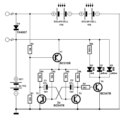
Flasher with LED high Intensity Circuit Diagram
This Flasher with LED high Intensity Circuit Diagram was designed as a flasher warning and was originally mounted on a bicycle. White LEDs are only recommended if the circuit is used as a bicycle front light and red LEDs only when used as a taillight. During the day, the two solar cells carry two 1.6 V AA batteries. In the darkness, the cell voltage disappears solar energy and batteries are automatically diverted to the circuit. The frequency of blinking (flashing) is about one per second.
Flasher with LED high Intensity Circuit Diagram

If you liked this article,Take a few Seconds to Share this and leave comments
Tuesday, September 9, 2014
Wesak Flasher with 6 Bulb

Wesak festival is getting near.So I decided to give you a very useful schema diagram this schema can drive 650Watt (Lamp 220V ) per Lamp channels.By using VR1 you can control the speed of your lamps.Here I have used very famous Ic 4017 and Ic NE 555.You can directly connect this schema for 230V.

Note
# This schema is 230V schema so this is not good for kids
# dont exceed 650W
Sunday, August 17, 2014
Headlight Flasher
Headlight FlasherThis schema was requested from an email. It will allow your car headlights to flash on and off at the same time or it will cause them to flash alternately. The schema is based on the 555 timer. It is used in the astable mode.
![]()
The 555 timer output will go high for an adjustable period of time and then turn off. It will then repeat the procedure.
The time is adjusted by R1. To hook up the schema to your car you must locate the positive wire from the fuse box to the headlights. Cut the wire and insert the relay contact and bypass switch. The bypass switch will allow you to bypass the relay contact for normal headlight operation. In the alternateing headlight configuration you must cut the positive wire to each headlight and wire in the relay contact.
Read More..
The 555 timer output will go high for an adjustable period of time and then turn off. It will then repeat the procedure.
The time is adjusted by R1. To hook up the schema to your car you must locate the positive wire from the fuse box to the headlights. Cut the wire and insert the relay contact and bypass switch. The bypass switch will allow you to bypass the relay contact for normal headlight operation. In the alternateing headlight configuration you must cut the positive wire to each headlight and wire in the relay contact.
Monday, August 11, 2014
Long time LED Flasher circuit diagram

Today Im going to going to show you a very wonderful schema diagram .The special thing of this schema is this schema can light up a LED more than the normal time.Sometimes it will light up our LED more than one month.so I suppose this would be a good news for you guys.Here I have used very common Transistor 2N3904.When I was making this schema I turned about 20 turns around the toroid. the wire was a small schema wire.

Note
# Build this schema on a PCB
# Dont use more than 1.5V
Sunday, August 10, 2014
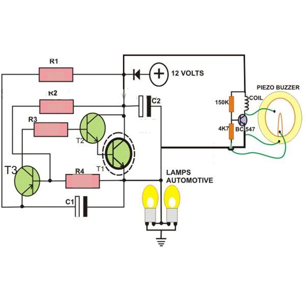
2 Pin Automobile Indicator Lamp Flasher Circuit with Buzzer

If you want to make a flasher unit for you motorbike then this schema is just for you. This simple turn signal flasher schema can be easily built and installed in any two wheelers for the desired actions. The schema employs just two 2-pins instead of 3 as found in other flasher diagram. Once installed, the schema will faithfully flash the side indicator lights whenever the intended function is switched ON. The schema also incorporates an optional buzzer schema which can be also included for getting a beeping sound in response to the flashing of the lamps.
Parts List
R1, R2, R3 = 10K
R4= 33K
T1 = D1351,
T2 = BC547,
T3 = BC557,
C1, C2 = 33uF.25V
L1 = Buzzer Coil
Subscribe to:
Posts (Atom)